


How to use the demo functions of IGEP Radar devices
From IGEP - ISEE Wiki
Contents
[hide]Overview
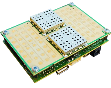
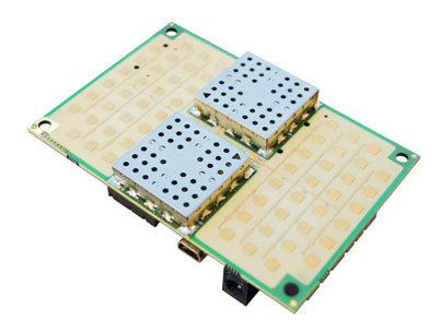
Some IGEP Radar solutions, such IGEP RADAR LAMBDA and IGEP RADAR EPSILON include a demo software with some basic functions and source examples to help developers getting started with the IGEP Radar Technology.
In this tutorial we are going to use these demo functions.

|
Please, notice that the web interface application of IGEP Radar solutions do not use the demo algorithms. Instead, the system uses advanced algorithms developed by the ISEE Radar Team to improve the performance. However, the included demo functions will allow users to create their first own applications from source as a starting point.
If you are interested in using the advanced algorithms you can contact with the ISEE Radar Team. |
Requirements
In this tutorial you will need:
- IGEP RADAR LAMBDA or IGEP RADAR EPSILON
- A computer with Ethernet or Wireless connection
Features and demo functions
The demo functions include some useful functionalities such:
- Configuration of the I/O
- Configuration of the DDS modulation
- Pre-start DDS modulation
- Capture of ADC samples
- Remove of DC component
- Calculation of FFT
- Basic Signal processing
Source code
The software also includes the source of the demo functions, so you can edit the code and add your own functionalities to fit any system. The functions that are included in the source code directory are:
radar_adc
radar_dcwindow
radar_dds
radar_fft
radar_maxfft
First steps
Connect via SSH
To connect your computer with your IGEP Radar solution you must remember the default network connectivity:
You IGEP RADAR solution has some default network configurations, based on the IGEP Firmware Yocto configuration:
| IGEP RADAR LAMBDA | IGEP RADAR EPSILON | |
| Default Configuration |
 |
 |
 |
static 192.168.5.1 static 192.168.2.232 DHCP (client) http://radar (Windows) http://radar.local (Linux & Mac) |
N/A |
| |
SSID: IGEP_xxxx (ad-hoc) static 192.168.6.1 DHCP (server) http://radar (Windows) http://radar.local (Linux & Mac) | |
| |
Using USB ethernet gadget to communicate | |
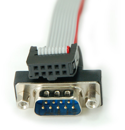 |
Using serial debug port to communicate | |
 |
How to setup Marvell bluetooth | |
All the peripherals can be configured with your own parameters.
In this tutorial we are going to connect to your IGEP Radar solution via Ethernet or Wifi.
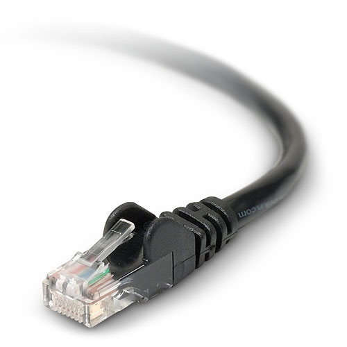
Plug an Ethernet cable between your IGEP Radar solution and your computer or connect to the IGEP_xxxx ad-hoc wireless network of your device.
To use the demo applications, you must establish a SSH connection with your IGEP Radar. This can be done via Ethernet, Wireless, USB, etc.
In this tutorial we are going to use Putty (an SSH client) over Ethernet, but you can use any program or interface that you are familiar with.
If you need help about how to install Putty and connecting via Ethernet or Wireless, now its time to jump to this articles:
At the end of this process you should have in your computer a system console of your IGEP Radar. You can log in with username: root ; password: [none: press enter]
Using the demo functions
There is a functional example script that launches the demo functions.
This script captures ADC sample, starts DDS modulation, calculates the FFT and does simple signal processing, as it searches position of maximum peak of FFT. To launch this script follow these instructions:
cd /home/root/radar
./demo-lambda.sh #If you are using IGEP RADAR LAMBDA
or
./demo-epsilon.sh #If you are using IGEP RADAR EPSILON
The script source is similar to this:
#!/bin/sh

# DEBUG enable "set -x"
#set -x

# Configure I/O
./radar_init.sh

# Configure DDS modulation

echo 0 > /sys/class/gpio/gpio162/value
./radar_dds -d /dev/spidev4.0
echo 1 > /sys/class/gpio/gpio162/value

# Pre-start DDS modulation
echo 1 > /sys/class/gpio/gpio140/value

# It captures  ADC sample and starts DDS modulation. It saves samples to "adquisition.txt" file
./radar_adc -d /dev/spidev4.0 > adquisition.txt

# End DDS modulation
echo 0 > /sys/class/gpio/gpio140/value

# It adapts capured data ("adquisition.txt" file)  removing DC component and selecting window of samples. It saves preprocessed sampling data to "data.txt" file
./radar_dcwindow -L adquisition.txt -B 1000 -E 1700 > data.txt

# It calculates FFT
./radar_fft -L data.txt -M 4 > fft.txt

# It does simple signal processing  ( it searches position of maximum peak of FFT )
./radar_maxfft -L fft.txt
When the script ends it shows you the result of the process:
./demo-lambda.sh
dds config: 0E8F C000 D3C0 2050 3000 1200 6090
13
You can read and manage the exported files with:
cat adquisition.txt
cat fft.txt
Source code available
The source code of all these functions is available at the same demo sofware. Check the source folder and list the files:
cd /home/root/radar/source/
ls
You can edit the C source code of these functions to fit your application requirements.
If you want to start developing your own application we recommend you to use the IGEP SDK Virtual Machine, a complete virtual machine that includes many IDE's and other resources that will help you developing under the IGEP Technology.
For more information about it visit the IGEP SDK Virtual Machine article.