Difference between revisions of "What can I do with IGEP BERLIN"
From IGEP - ISEE Wiki
m (→Get sound in (audio in)) |
m (→How to Telit Modem) |
||
| (7 intermediate revisions by 2 users not shown) | |||
| Line 64: | Line 64: | ||
*Power up the modem using the next commands: | *Power up the modem using the next commands: | ||
| − | + | <pre>echo 0 > /sys/class/gpio/gpio145/value | |
| − | + | echo 1 > /sys/class/gpio/gpio163/value | |
| − | + | sleep 1 | |
| − | + | echo 0 > /sys/class/gpio/gpio163/value</pre> | |
*Once the modem is on (led near power button is blinking now), you can interact with it via UART 2. | *Once the modem is on (led near power button is blinking now), you can interact with it via UART 2. | ||
| Line 194: | Line 194: | ||
$ amixer -c 0 sset 'Analog Left AUXL' cap | $ amixer -c 0 sset 'Analog Left AUXL' cap | ||
| − | You can record audio in with the application arecord, for example: | + | You can record audio in with the application arecord, for [http://www-mmsp.ece.mcgill.ca/Documents/AudioFormats/WAVE/Samples/AFsp/M1F1-int32WE-AFsp.wav example]: |
$ arecord -t wav -c 2 -r 44100 -f S16_LE -v audio-in.wav | $ arecord -t wav -c 2 -r 44100 -f S16_LE -v audio-in.wav | ||
| Line 250: | Line 250: | ||
A detailed guide on how use wifi can be found by following this link: [[Using USB ethernet gadget to communicate]] | A detailed guide on how use wifi can be found by following this link: [[Using USB ethernet gadget to communicate]] | ||
| + | == How to read analog values (ADC) == | ||
| + | |||
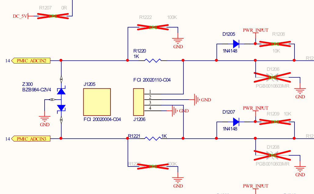
| + | IGEP BERLIN provides 2 analog inputs on J1206: Maximum allowed analog voltage is 1V8. | ||
| + | |||
| + | [[Image:BASE_BERLIN_CONNECTORS.png|right|300px]] | ||
| + | |||
| + | To protect the ADC input for higher voltages than 1V8, exist a diode protection (Z300). See diagram on the right side. | ||
| + | |||
| + | [[Image:BERLIN_ADC_SCHEMA.png|right|300px]] | ||
| + | |||
| + | To prove the lectures, you have examples codes written in phyton in the ISEE GIT. | ||
| + | |||
| + | [http://git.isee.biz/?p=pub/scm/igep_qa.git;a=blob_plain;f=igep_qa/helpers/madc.py;hb=HEAD Downlaod Python example] | ||
| + | |||
| + | [http://git.isee.biz/?p=pub/scm/igep_qa.git;a=tree;f=igep_qa/helpers;h=e0671966af9f539bdd7628e101c181d8e74dc506;hb=HEAD ->Link to GIT directory] | ||
| + | |||
| + | To read the ADC2 or ADC3 you have to modify one line of code at end of document for the channel 2 or 3. | ||
| + | |||
| + | madc = QMadc(2) or madc = QMadc(3) | ||
| + | |||
| + | You have another example written in c. | ||
| + | |||
| + | [[File:BERLIN_ADC.tar.gz]] | ||
| + | |||
| + | Warning: There is a small deviation in reading values near to 1V8 due to this protection. | ||
| + | The TPS65950 datasheet describes chip can support up to 2.5V at the ADC input . | ||
| + | Datasheet: http://www.ti.com/lit/ds/symlink/tps65950.pdf | ||
| + | Under his responsibility can desolder for more accurate readings. | ||
| + | |||
| + | == How to operate USER LED's == | ||
| + | |||
| + | On BASE0010 the two leds are available via gpio 19 and 22. See the example below: | ||
| + | |||
| + | === For D103 LED USER1(GPIO22): === | ||
| + | |||
| + | We publish the virtual file system to configure elements of the chip via the Linux kernel | ||
| + | mount -t debugfs none /sys/kernel/debug/omap_mux | ||
| + | Set the pin as function gpio22 | ||
| + | echo 0x104 > /sys/kernel/debug/omap_mux/etk_d8 | ||
| + | Do gpio22 accessible | ||
| + | echo 22 > /sys/class/gpio/export | ||
| + | Configure the pin as output | ||
| + | echo out > /sys/class/gpio/gpio22/direction | ||
| + | |||
| + | LED ON: echo 1 > /sys/class/gpio/gpio22/value | ||
| + | LED OFF:echo 0 > /sys/class/gpio/gpio22/value | ||
| + | |||
| + | === For D103 LED USER2 (GPIO19): === | ||
| + | |||
| + | echo 19 > /sys/class/gpio/export | ||
| + | echo out>/sys/class/gpio/gpio19/direction | ||
| + | |||
| + | LED ON: echo 1 > /sys/class/gpio/gpio19/value | ||
| + | LED OFF:echo 0 > /sys/class/gpio/gpio19/value | ||
| + | |||
| + | |||
{{Template:Navigation/IGEP Technology Guides/What can I do/Ending}} | {{Template:Navigation/IGEP Technology Guides/What can I do/Ending}} | ||
[[Category:IGEP Technology Devices Guides]] | [[Category:IGEP Technology Devices Guides]] | ||
Latest revision as of 13:53, 9 September 2015
|
|
Overview
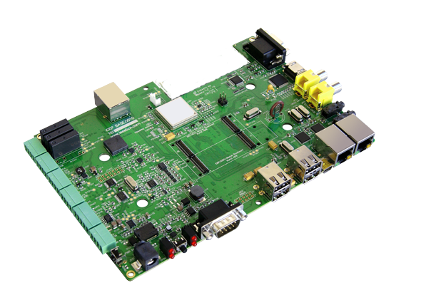
This is the 2/3 chapter of IGEP BERLIN Expansion Tutorial Guide.
We will learn some basic tasks.
Contents
- 1 Overview
- 2 What can I do
- 2.1 How to use TFT and Touchscreen
- 2.2 How to use DVI
- 2.3 How to Telit Modem
- 2.4 How to use to use TVP5151 Video Decoder
- 2.5 How to use EEPROM
- 2.6 How to use CAN Bus
- 2.7 How to use serial console
- 2.8 How to use RS-485
- 2.9 Get sound in (audio in)
- 2.10 Get sound out (audio out)
- 2.11 How to use the USB OTG
- 2.12 How to read analog values (ADC)
- 2.13 How to operate USER LED's
What can I do
How to use TFT and Touchscreen
IGEP BERLIN Expansion supports SEIKO 7” LCD screen. Use J200, J203 and J204 connectors to attach screen. See image for more details.By default, Seiko screen is supported in IGEP BERLIN. However open igep.ini, you can do this checking following kernel cmdline parameter:
omapdss.def_disp=lcd-70
Finally, edit file: (rootfs)/etc/X11/xorg.conf to enable default touchscreen calibration, xorg.conf touchscreen and ServerLayout sections should look like this:
Section "InputDevice"
        Identifier      "Seiko Touchscreen"
        Driver          "evdev"
        Option          "Device"                 "/dev/input/touchscreen0"
#       Option          "Calibration"   "138 3923 311 3962"
EndSection
Section "ServerLayout"
	Identifier	"Builtin Default Layout"
	Screen		"Builtin Default fbdev Screen 0"
      InputDevice    "Seiko Touchscreen"
	Option		"BlankTime"	"0"
	Option		"StandbyTime"	"0"
	Option		"SuspendTime"	"0"
	Option		"OffTime"	"0"
EndSection
How to use DVI
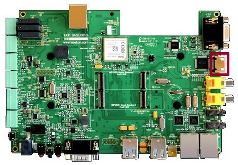
IGEP BERLIN has a HDMI connector with a DVI-D interface. IGEP Firmware configures video output with touch screen resolution. For this reason, you should change it to adapt for HDMI standard resolution, you can edit following kernel cmdline parameter.
;omapdss.def_disp=lcd-70
omapfb.mode=dvi:1280x720MR-16@60
How to Telit Modem
|
|
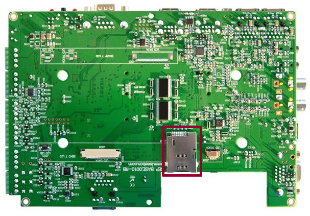
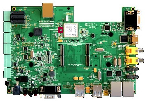
| GSM-GPRS antenna (highly recommended) | SIM card reader |
IGEP BERLIN Expansion integrates a GSM/GPRS modem to make phone calls or to send SMS or to write and read data from it, etc. Telit modem is not supported by default in IGEP BERLIN. Configure this adding following kernel cmdline parameter
buddy.modem=yes
- Power up the modem using the next commands:
echo 0 > /sys/class/gpio/gpio145/value
echo 1 > /sys/class/gpio/gpio163/value
sleep 1
echo 0 > /sys/class/gpio/gpio163/value
- Once the modem is on (led near power button is blinking now), you can interact with it via UART 2.
You can use Microcom to comunicate with it from the serial debug console:
$ microcom -s 115200 /dev/ttyO1
- To check the modem status use the command:
at
- Answer should be OK.
- Now unlock it by inserting your SIM card PIN number. Use the command:
at+cpin=<PIN>
- If you correctly inserted the PIN number, the answer should be OK. If you fail more than 3 times, your SIM card will lock and you will have to insert PUK number.
- Now you are ready to use the GSM/GPS modem.
How to use to use TVP5151 Video Decoder

|
IGEP COM MODULE AND IGEP BERLIN doesn't support video decoder |
Configure TVP5151
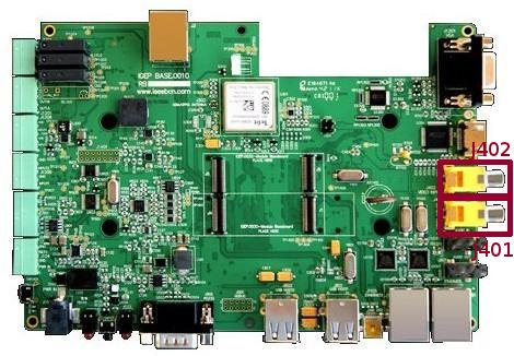
- Plug some peripheral with video composite output in J402 rca connector, see the image for more details.
- Connect a screen, for example HDMI monitor.
- Refresh repositories and accept it.
$ zypper ref
- Install video4linux2 plugin
$ zypper in gst-plugins-good-video4linux2
Play with TVP5151
- Load OMAP ISP kernel module
$ modprobe omap3-isp
- Configure ISP, for PAL resulution use 720x576 for NTSC resolution use 720x480:
$ media-ctl -r -l '"tvp5150 3-005d":0->"OMAP3 ISP CCDC":0[1], "OMAP3 ISP CCDC":1->"OMAP3 ISP CCDC output":0[1]'
$ media-ctl -v --set-format '"tvp5150 3-005d":0 [UYVY 720x480]'
$ media-ctl -v --set-format '"OMAP3 ISP CCDC":0 [UYVY 720x480]'
$ media-ctl -v --set-format '"OMAP3 ISP CCDC":1 [UYVY 720x480]'
- Export display
$ export DISPLAY=:0.0
- Launch gstreamer
$ gst-launch-0.10 -v v4l2src device=/dev/video2 queue-size=8 ! video/x-raw-yuv,format=\(fourcc\)UYVY,width=720,height=480 ! ffmpegcolorspace ! autovideosink
- Now you can see in your IGEP screen a result similar like this
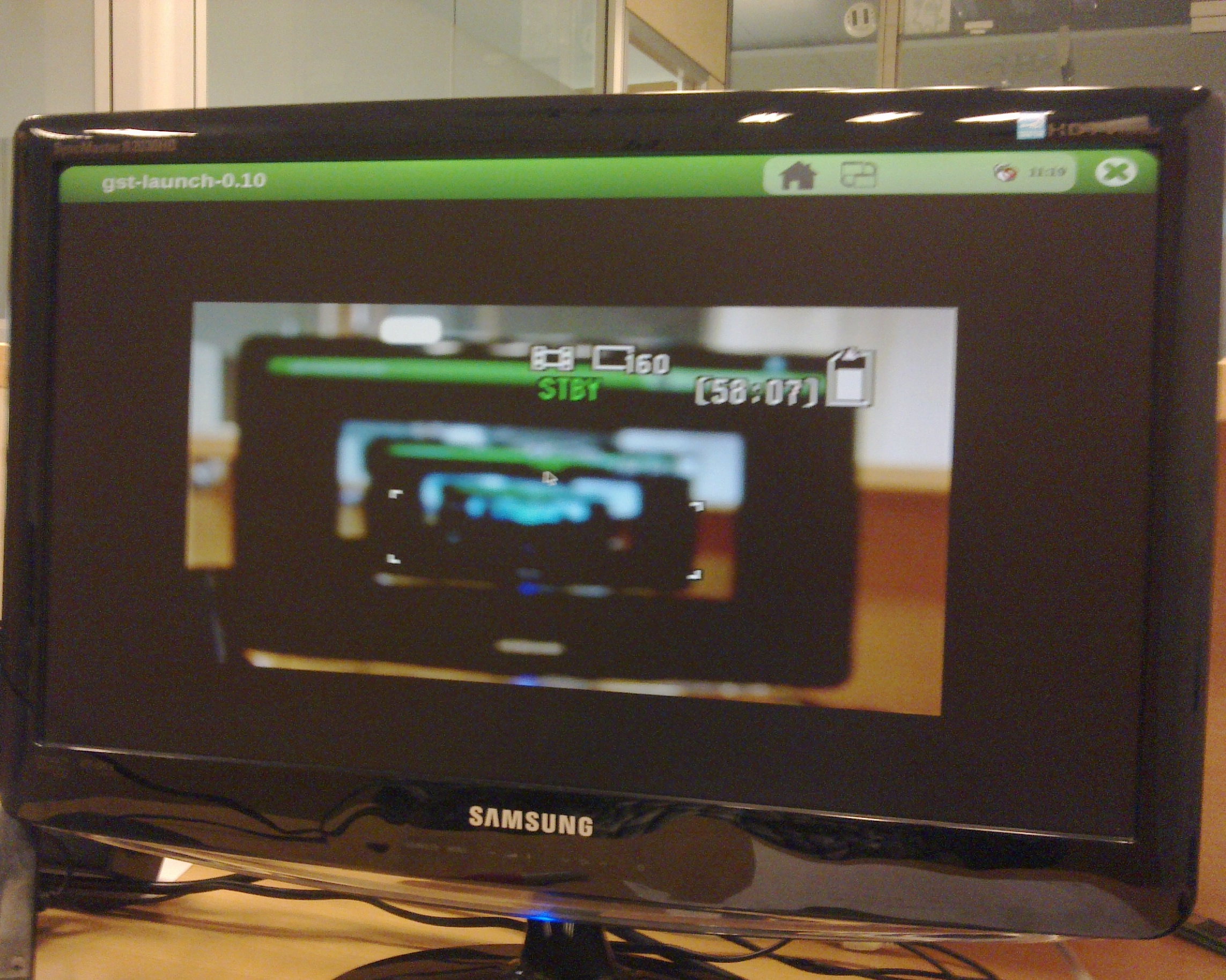
|
From How to setup tvp5151 video decoder
How to use EEPROM
IGEP BERLIN Expansion includes a serial EEPROM, provides 1KB of user data storage. EEPROM is connected through I2C2 of OMAP3 processor at address 0x50.
The following example writes the value 0x22 to register 0x10 of device 0x50 on i2c bus 3:
$ i2cset -f -y 3 0x51 0x10 0x22
$ i2cget -f -y 3 0x51 0x10
From How to use EEPROM
How to use CAN Bus
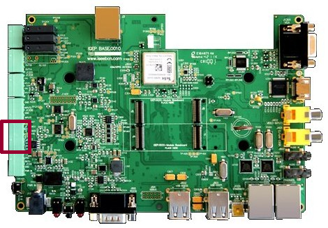
IGEP BERLIN Expansion integrates a CAN peripheral. Connect any CAN bus device or network to the CAN bus connector (J901).You have to connect the two boards like this:
IGEP BERLIN 1        IGEP BERLIN 2
.---                 .---
| 1 |------------------| 1 |  CANH : CAN High-Level Voltage I/O
| 2 |------------------| 2 |  CANL: CAN Low-Level Voltage I/O
| 3 |------------------| 3 |  GND : Ground
| 4 |-X            X-| 4 |
| 5 |-X            X-| 5 |
.---                 .---
Now you can set up the interface (on all boards when using multiple IGEP BERLIN connected to a CAN network simultaneously):
$ ip link set can0 up type can bitrate 125000
If you want to receive CAN data, use:
$ candump can0
If you want to send CAN data, use:
$ cansend can0 -i 0x123 0xaa 0xbb 0xcc 0xdd
On the receiver side, you must see the following messages:
can0 123 [4] aa bb cc dd
Switch roles and try it again
How to use serial console
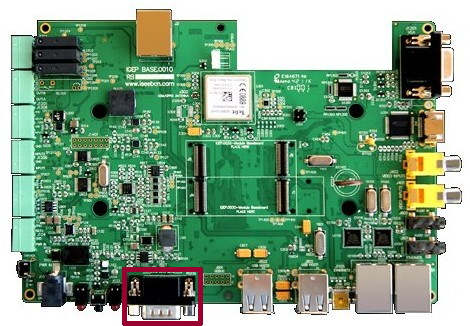
Connect a DB9 cable between IGEP PARIS and Host PC. Open the serial on your PC using your preferred serial communications program (minicom) and configure the port as follows:- 115200
- 8N1
- no flow control (either software or hardware)
Open the serial port and the debug shell prompt should appear.
A detailed guide on how to connect via serial debug port can be found by following this link: Using serial debug port to communicate
How to use RS-485
This How-To is meant to be a starting point for people to learn to use RS-485 port on IGEP devices as quickly and easily as possible. We use IGEP YOCTO Firmware and RS485 example which describe how to setup and write data on the RS-485 port.
A detailed guide on how use UARTS can be found by following this link: How to use RS485
Get sound in (audio in)
External Audio input devices, such as a powered microphone or the audio output of a PC or MP3 player, can be connected to the via a 3.5mm jack (Audio IN).
Note that the board has been designed to use Line In for the audio input which means users need to add some type of pre-amp for a microphone to work or use a powered microphone. For a pre-amp for a microphone you can use MAX9812.
Enable capture:
$ amixer -c 0 sset 'Analog Right AUXR' cap
$ amixer -c 0 sset 'Analog Left AUXL' cap
You can record audio in with the application arecord, for example:
$ arecord -t wav -c 2 -r 44100 -f S16_LE -v audio-in.wav
Following output is expected on console:
Recording WAVE 'audio-in.wav' : Signed 16 bit Little Endian, Rate 44100 Hz, Stereo
Plug PCM: Hardware PCM card 0 'TWL4030' device 0 subdevice 0
Its setup is:
stream       : CAPTURE
access       : RW_INTERLEAVED
format       : S16_LE
subformat    : STD
channels     : 2
rate         : 44100
exact rate   : 44100 (44100/1)
msbits       : 16
buffer_size  : 32768
period_size  : 2048
period_time  : 46439
tick_time    : 7812
tstamp_mode  : NONE
period_step  : 1
sleep_min    : 0
avail_min    : 2048
xfer_align   : 2048
start_threshold  : 1
stop_threshold   : 32768
silence_threshold: 0
silence_size : 0
boundary     : 1073741824
When ever you think you want to stop recording just press CTRL+C
Get sound out (audio out)
Connect an external output audio device to the 3.5mm jack Audio Out connector in the board, such as external stereo powered speakers.
The amplifiers for the headset output are disabled by default, so the first thing you'll do is enable these amplifiers with:
$ amixer set -D hw:0 'Headset' 0dB
$ amixer set -D hw:0 'HeadsetL Mixer AudioL2' on
$ amixer set -D hw:0 'HeadsetR Mixer AudioR2' on
Then you can easily play a *.wav sound with the application Aplay, for example:
$ aplay audio-in.wav
How to use the USB OTG
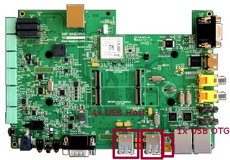
In order to act in host mode and add some peripherals like keyboard, mouse or pendrives you require a special cable that grounds the ID pin. Since the OTG port only provides 100mA of power a USB hub is recommended.Though a common USB Standard-A to Mini-B type cable the port acts as a device. In this mode you can connect to the board using the USB Ethernet Gadget. Use this cable between your computer and the target board and connect with:
$ ssh root@192.168.7.1
A detailed guide on how use wifi can be found by following this link: Using USB ethernet gadget to communicate
How to read analog values (ADC)
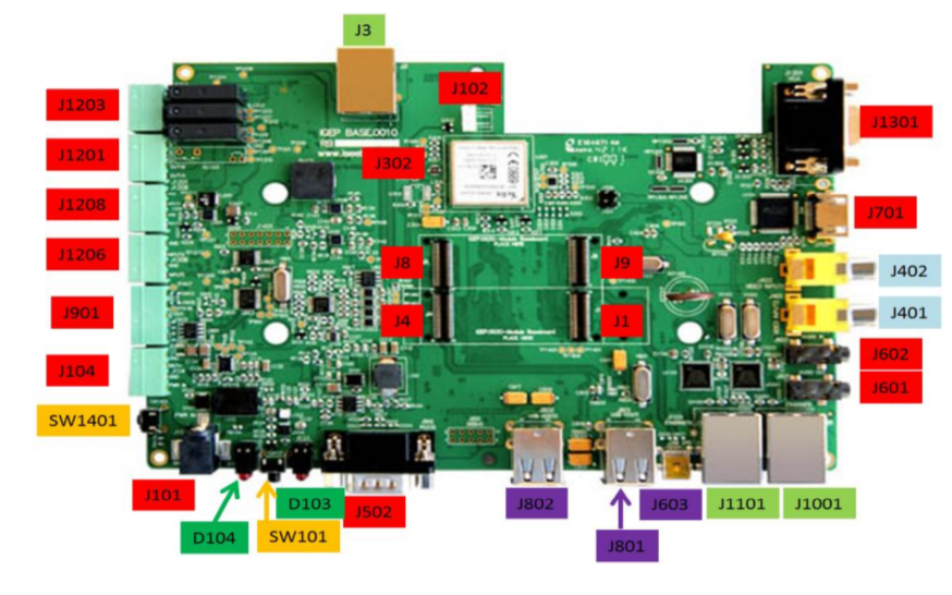
IGEP BERLIN provides 2 analog inputs on J1206: Maximum allowed analog voltage is 1V8.
To protect the ADC input for higher voltages than 1V8, exist a diode protection (Z300). See diagram on the right side.
To prove the lectures, you have examples codes written in phyton in the ISEE GIT.
To read the ADC2 or ADC3 you have to modify one line of code at end of document for the channel 2 or 3.
madc = QMadc(2) or madc = QMadc(3)
You have another example written in c.
Warning: There is a small deviation in reading values near to 1V8 due to this protection.
The TPS65950 datasheet describes chip can support up to 2.5V at the ADC input .
Datasheet: http://www.ti.com/lit/ds/symlink/tps65950.pdf
Under his responsibility can desolder for more accurate readings.
How to operate USER LED's
On BASE0010 the two leds are available via gpio 19 and 22. See the example below:
For D103 LED USER1(GPIO22):
We publish the virtual file system to configure elements of the chip via the Linux kernel
mount -t debugfs none /sys/kernel/debug/omap_mux
Set the pin as function gpio22
echo 0x104 > /sys/kernel/debug/omap_mux/etk_d8
Do gpio22 accessible
echo 22 > /sys/class/gpio/export
Configure the pin as output
echo out > /sys/class/gpio/gpio22/direction
LED ON: echo 1 > /sys/class/gpio/gpio22/value
LED OFF:echo 0 > /sys/class/gpio/gpio22/value
For D103 LED USER2 (GPIO19):
echo 19 > /sys/class/gpio/export
echo out>/sys/class/gpio/gpio19/direction
LED ON: echo 1 > /sys/class/gpio/gpio19/value
LED OFF:echo 0 > /sys/class/gpio/gpio19/value
You have successfully completed this chapter of the guide.
|

|
If you have any question, don't ask to ask at the IGEP Community Forum or the IGEP Community Chat | 
|


