Getting started with IGEP RADAR LAMBDA
From IGEP - ISEE Wiki
| |
| |||||||||
In this first chapter, we will learn:
- Connect the radar to a PC via Ethernet.
- Boot the board with the default firmware.
- Make first measurements using web server demo application.
Upon completion, you will be ready to continue with chapter 2/3 that explains more advanced tasks.
Contents
[hide]

|
If you are using an old version of the IGEP Radar software, please check the Legacy Software section for specific tutorials for your version. |
Requirements
In this tutorial we are going to use the following materials:
- IGEP RADAR LAMBDA with its power supply
- Network cable
- PC with keyboard, mouse and monitor
Getting started
Please follow the next steps as indicated. You could change later the way you use the radar but it is very important you follow these instructions at least once for the first time. With this exercise you will start to understand how the radar works and most of your questions will be solved in a few minutes.
Identify your Radar
First of all you should identify which kind of radar do you have.
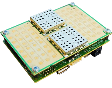
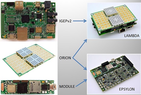
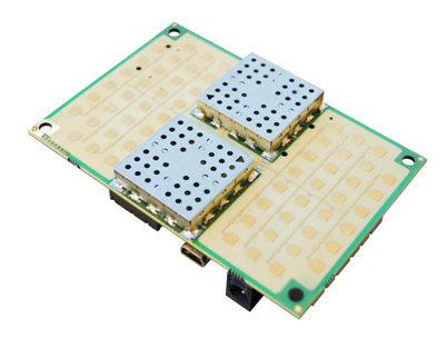
IGEP RADAR SENSOR ORION can be an stand alone radar sensor or it can be plugged with any of 2 different processor boards: IGEPv2 or IGEP COM MODULE.
When combined with IGEPv2 the result is called IGEP RADAR LAMBDA, while when combined with IGEP COM MODULE the result is called IGEP RADAR EPSILON.
The next picture show both combinations:
Identify the different parts of the radar sensor ORION
It is very important you are able to identify the basic parts of the radar in order to avoid wrong set ups of measurement.
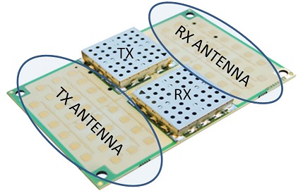
IGEP Radar Technology is designed for using World-Wide 24GHz ISM Band (K-Band).
The next picture show which is the 24GHz transmitting antenna, the receiving antenna, the transmitter (TX) and the receiver (RX):
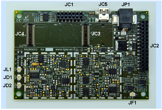
You can also take a look at the bottom face:
JL1 gives you access to the VCO signal
JD1 is the modulation signal
JD2 is the synchronism (you can use this signal to visualise the others on an oscilloscope)
JF1 is the IF signal
JC2 is the expansion connector for IGEPv2
JC4 and JC3 are the expansion connectors for IGEP COM MODULE
JP1 is the power connector
Place the Radar on a stable surface
Place the radar over your desk and oriented with the ORION board (antenna) facing a wall of your office with nothing in between in order to have a clearly dominant reflection. A distance of about 3 meters between the radar and the wall would be good to make a first measurement.
Network & Connectivity
You IGEP RADAR solution has some default network configurations, based on the IGEP Firmware Yocto configuration:
| IGEP RADAR LAMBDA | IGEP RADAR EPSILON | |
| Default Configuration |
||
| Ethernet | static 192.168.5.1 static 192.168.2.232 DHCP (client) http://radar (Windows) http://radar.local (Linux & Mac) |
N/A |
| Wifi | SSID: IGEP_xxxx (ad-hoc) static 192.168.6.1 DHCP (server) http://radar (Windows) http://radar.local (Linux & Mac) | |
| USB | Using USB ethernet gadget to communicate | |
| UART | Using serial debug port to communicate | |
| Bluetooth | How to setup Marvell bluetooth | |
All the peripherals can be configured with your own parameters.
In this tutorial we are going to connect to your IGEP Radar solution via Ethernet or Wifi.
Plug an Ethernet cable between your IGEP Radar solution and your computer or connect to the IGEP_xxxx ad-hoc wireless network of your device.
Source Power
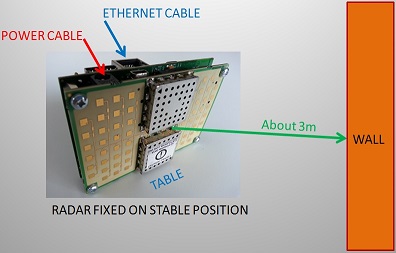
Now, before you apply the source power to the radar, ensure the equipment is fixed over your desk and the cables do not move the radar. Once the radar is fixed facing to the wall, you can power it through any of its power connectors: J200 on IGEPv2 board or JP1 on ORION board. Remember you can power the radar through any of both connectors but never apply power to both at the same time. Here there is a diagram of an ideal measurement over a wall:
Radar Field of View
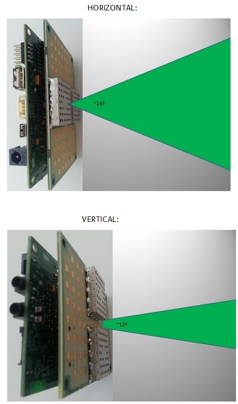
Be aware of the radar angle of detection. The radar will only detect objects within its field of view. The angle of detection is about 24º in horizontal direction and about 12º in vertical direction:
Wait few minutes
Once you apply power, please wait a few minutes while IGEPv2 board boots with the default firmware flashed on the internal memory. You will see LEDs from IGEPv2 blinking until system has booted, then you will see a fixed lighted green LED.
Run Web Browser on PC
Run a web browser on your PC with the ability to work with CANVAS (HTML5). We recommend the use of "Mozilla FireFox" web browser that you can install and download for free at: http://www.mozilla.org/

|
If you are using an old version of the IGEP Radar software, please check the Legacy Software section for specific tutorials for your version. |
Connect to Radar IP
To connect to the radar, open a new browser window and type any of these URL addresses:
- http://radar (Windows)
- http://radar.local (Linux or Mac)
or directly to any of these IP addresses (remember to setup your network adapter in your computer to the same network subnet):
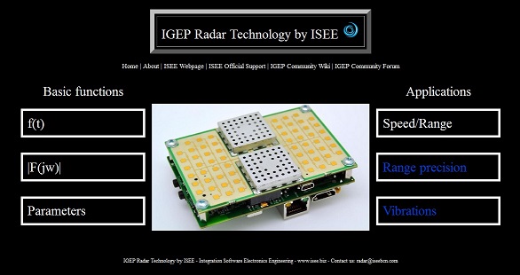
If the radar has already started you will see the Home page of the web radar application demo, if not, please be patient and wait a little bit more until the radar starts. You will see a home page similar to this one:
Congratulations!
You have successfully connected with radar. Now you can start to make measurements and learn about radar possibilities.
Do not worry if your home page differs from the picture, there are some different format versions but are equivalent in features.
You have successfully completed this chapter of the guide.
| |

|
If you have any question, don't ask to ask at the IGEP Community Forum or the IGEP Community Chat | 
|


