Difference between revisions of "What can I do with IGEPv2 EXPANSION"
From IGEP - ISEE Wiki
m (→How to use Telit Modem) |
m (→How to use TVP5151 Video Decoder) |
||
| Line 74: | Line 74: | ||
''From [[How to use Telit Modem]]'' | ''From [[How to use Telit Modem]]'' | ||
| − | == How to use TVP5151 Video Decoder <br> | + | == How to use TVP5151 Video Decoder == |
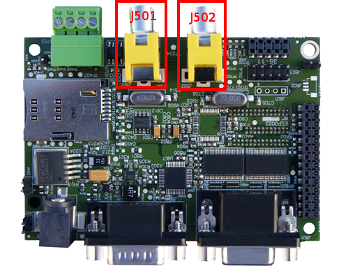
| + | [[Image:Igepv2expvideocompositeconnector.PNG|right|200px]]IGEPv2 Expansion integrates two composite video connectors to decode analog input signal. Plug some peripheral with video composite output in J501 rca connector, see the image for more details..<br> | ||
=== Configure TVP5151 === | === Configure TVP5151 === | ||
| − | + | ||
=== Play with TVP5151 === | === Play with TVP5151 === | ||
| − | + | ||
''From [[How to setup tvp5151 video decoder]]'' | ''From [[How to setup tvp5151 video decoder]]'' | ||
Revision as of 17:32, 10 September 2012
| |
| |||||||||
Contents
[hide]Overview
This is the 2/3 chapter of IGEPv2 Expansion Tutorial Guide.
We will learn some basic tasks.
What can I do
How to use TFT and Touchscreen
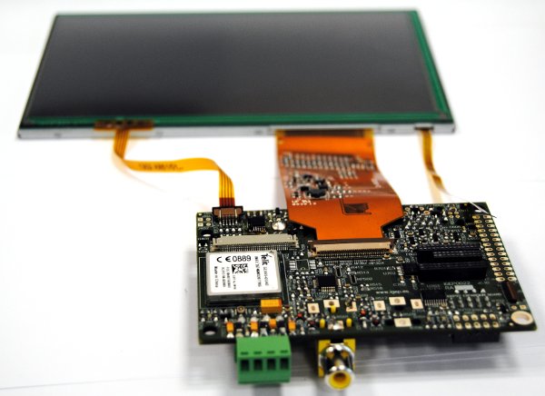
IGEPv2 Expansion supports SEIKO 7” or POWERTIP 4.3” LCD screen. Use J301 connector for POWERTRIP 4.3" or use J302, J303 and J304 connector for SEIKO 7".Seiko and Powertip touch screens are not supported by default in IGEPv2. Use the following steps for it:
Edit igep.ini file to configure your touch screen, you can do this adding following kernel cmdline parameter
- In Seiko screen add the following line:
omapdss.def_disp=lcd-70
- In Powertip screen add the following line:
omapdss.def_disp=lcd-43
How to use serial console
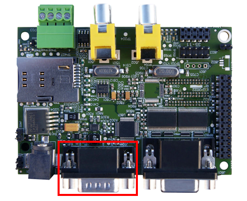
IGEPv2 Expansion integrates a DB9 RS232 connector. Now you need a Null-Modem DB9 male-make serial cable. Connect the cable between the board and your PC. Open the serial on your PC using your preferred serial communications program (minicom) and configure the port as follows:- 115200
- 8N1
- no flow control (either software or hardware)
Open the serial port and the debug shell prompt should appear.
A detailed guide on how to connect via serial debug port can be found by following this link: Using serial debug port to communicate
How to use Telit Modem
|
|
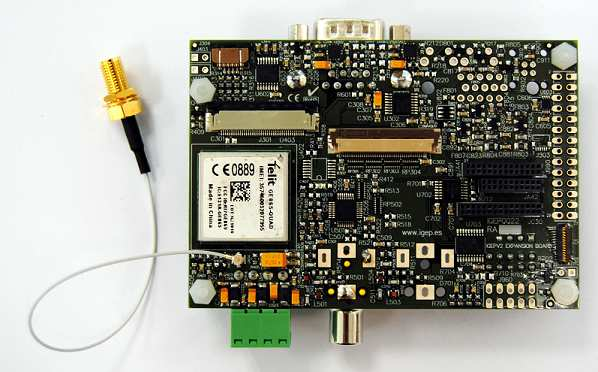
| GSM-GPRS antenna (highly recommended) | SIM card reader |
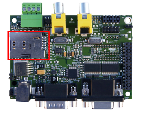
IGEPv2 Expansion integrates a GSM/GPRS modem to make phone calls or to send SMS or to write and read data from it, etc. Telit modem is not supported by default in IGEPv2 Expansion. Configure this adding following kernel cmdline parameter
buddy.modem=yes
- Power up the modem using the next commands:
echo 0 > /sys/class/gpio/gpio140/value
echo 1 > /sys/class/gpio/gpio141/value
sleep 1
echo 0 > /sys/class/gpio/gpio141/value
- Once the modem is on (led near power button is blinking now), you can interact with it via UART 2.
You can use Microcom to comunicate with it from the serial debug console:
microcom -s 115200 /dev/ttyO1
- To check the modem status use the command:
at
- Answer should be OK.
- Now unlock it by inserting your SIM card PIN number. Use the command:
at+cpin=<PIN>
- If you correctly inserted the PIN number, the answer should be OK. If you fail more than 3 times, your SIM card will lock and you will have to insert PUK number.
- Now you are ready to use the GSM/GPS modem.
How to use TVP5151 Video Decoder
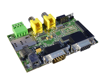
IGEPv2 Expansion integrates two composite video connectors to decode analog input signal. Plug some peripheral with video composite output in J501 rca connector, see the image for more details..Configure TVP5151
Play with TVP5151
From How to setup tvp5151 video decoder
How to use EEPROM
Basic
The following writes the value 0x22 to register 0x10 of device 0x50 on i2c bus 2:
i2cset -f -y 2 0x50 0x10 0x22
i2cget -f -y 2 0x50 0x10
Know more
See also: i2dump(8), i2cget(8) and i2cset(8) man page
From How to use EEPROM
How to use CAN bus
You have to connect the two boards like this:
IGEPv2 1             IGEPv2 2
.---                 .---
| 1 |-X            X-| 1 |
| 2 |------------------| 2 |
| 3 |------------------| 3 |
| 4 |------------------| 4 |
.---                 .---
If this is your first time accessing CAN bus, check J702 jumper is not connected before follow this tutorial. If you don't have this jumper, don't worry because its function is only for testing.
Now you can set up the interface (on all boards when using multiple IGEPv2 EXPANSION connected to a CAN network simultaneously):
/bin/ip link set can0 up type can bitrate 125000
If you want to receive CAN data, use:
candump can0
If you want to send CAN data, use:
cansend can0 -i 0x123 0xaa 0xbb 0xcc 0xdd
On the receiver side, you must see the following messages:
can0 123 [4] aa bb cc dd
Switch roles and try it again
From How to use CAN bus
You have successfully completed this chapter of the guide.
| |

|
If you have any question, don't ask to ask at the IGEP Community Forum or the IGEP Community Chat | 
|
| |
| |||||||||


