

Difference between revisions of "What can I do with IGEPv2 EXPANSION"
From IGEP - ISEE Wiki
m |
|||
| Line 1: | Line 1: | ||
| − | + | = What can i do with igepv2 expansion = | |
| − | {| | + | {{Table/IGEP Technology Devices |
| − | | | + | |Tech_Family={{#lst:Template:Links|IGEPv2_EXPANSION_Tech_Family}} |
| − | | | + | |Tech_ID={{#lst:Template:Links|IGEPv2_EXPANSION_Tech_ID}} |
| − | |||
| − | |||
| − | |||
| − | |||
| − | |||
| − | |||
|Name={{#lst:Template:Links|IGEPv2_EXPANSION_Name}} | |Name={{#lst:Template:Links|IGEPv2_EXPANSION_Name}} | ||
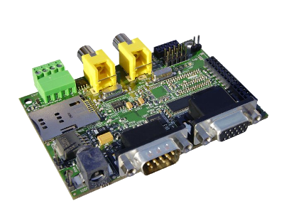
|Image={{#lst:Template:Links|IGEPv2_EXPANSION_Image}} | |Image={{#lst:Template:Links|IGEPv2_EXPANSION_Image}} | ||
|ISEE_MainPage={{#lst:Template:Links|IGEPv2_EXPANSION_ISEE_MainPage}} | |ISEE_MainPage={{#lst:Template:Links|IGEPv2_EXPANSION_ISEE_MainPage}} | ||
|ISEE_Hardware={{#lst:Template:Links|IGEPv2_EXPANSION_ISEE_Hardware}} | |ISEE_Hardware={{#lst:Template:Links|IGEPv2_EXPANSION_ISEE_Hardware}} | ||
| − | + | }} | |
| − | |||
| − | |||
| − | }} | ||
| + | <br> __TOC__ | ||
| − | + | <br> | |
| − | |||
| − | |||
| − | |||
| − | |||
| − | |||
| − | |||
| − | |||
| + | = Overview = | ||
| − | + | This is the 2/3 chapter of IGEPv2 Expansion Tutorial Guide. | |
| + | We will learn some basic tasks such add support to IGEPv2 Expansion, control some peripherals, etc.<br> | ||
| − | = | + | = What can I do<br> = |
| − | + | == How to use Serial communication (DB9 connector) == | |
| − | + | '''Basic''' | |
| + | RS232 link for UART 3 (/dev/ttyO2) can be obtained through J502 DB9 connector. You can use PuTTy to get a shell prompt to IGEP: | ||
| − | + | *Power up IGEPv2 | |
| + | *Open PuTTy. | ||
| + | *Choose Serial line. If you are running PuTTy on Windows, the Serial line will be like (COM1 or COM2 or COM3, etc.). If you are running PuTTy on Ubuntu, the Serial line will be like (/dev/ttyS0 or /dev/ttyS1 or /dev/ttyS3, etc.). Note that if you are using a USB->Serial converter, the Serial line will be like /dev/ttyUSB0 | ||
| + | *Configure Speed to 115200 | ||
| + | *Select Serial Connection type | ||
| + | *Press on Open button | ||
| + | *You will successfully started the console. | ||
| − | + | <br> | |
| − | |||
| − | |||
| + | {| cellspacing="1" cellpadding="1" width="200" border="1" | ||
| + | |- | ||
| + | | [[Image:IGEPV2EXPCHMDB9.png|250px]] | ||
| + | | [[Image:Remoteshellpromptdb9putty.jpg|250px]] | ||
| + | |} | ||
| − | + | '''Know more''' | |
| − | |||
| − | |||
| − | |||
| − | |||
| − | |||
| − | |||
| − | |||
| − | |||
| − | |||
| − | |||
| − | |||
| − | |||
| − | |||
| − | |||
| − | |||
| − | |||
| − | |||
| − | |||
| − | |||
| − | |||
| − | |||
| − | |||
| − | |||
| − | |||
| − | |||
| − | |||
| − | |||
| − | |||
| − | |||
| − | |||
| − | |||
| − | |||
| − | |||
| − | |||
| − | |||
| − | |||
| − | |||
| − | |||
| − | |||
| − | |||
| − | |||
| − | |||
| − | |||
| − | |||
| − | |||
| − | |||
| − | |||
| − | |||
| − | |||
| − | |||
| − | |||
| − | |||
| − | |||
| − | + | [[How to use UARTs|Read this tutorial]] to learn about UARTs. | |
| − | + | == How to use TFT and Touchscreen == | |
| − | + | Seiko a Powertip touch screens are not supported by default in IGEPv2. Use the following steps for it: | |
| − | + | *Log into IGEPv2 (via SSH, [http://labs.isee.biz/index.php/Getting_started_with_IGEPv2#Log_into_IGEPv2_via_Ethernet_interface as shown in the previous chapter]), and run the following commands: | |
| + | <pre>ssh root@192.168.5.1 | ||
| + | mkdir /tmp/temp | ||
| + | mount -t jffs2 /dev/mtdblock1 /tmp/temp | ||
| + | vi /tmp/temp/igep.ini </pre> | ||
| + | *In Seiko screen add the following line: | ||
| + | <pre>omapdss.def_disp=lcd-70</pre> | ||
| + | *In Powertip screen add the following line: | ||
| + | <pre>omapdss.def_disp=lcd-43</pre> | ||
| + | *Save changes and reboot your IGEP Device to finish it.<br> | ||
| − | + | == How to use Telit Modem == | |
| − | |||
| − | |||
| − | + | '''Basic''' | |
| − | + | Telit modem is not supported by default in IGEPv2. Use the following steps for it: | |
| − | * | + | *Log into IGEPv2 (via SSH, [http://labs.isee.biz/index.php/Getting_started_with_IGEPv2#Log_into_IGEPv2_via_Ethernet_interface as shown in the previous chapter]), and run the following commands: |
| − | + | <pre>ssh root@192.168.5.1 | |
| − | * | + | mkdir /tmp/temp |
| + | mount -t jffs2 /dev/mtdblock1 /tmp/temp | ||
| + | vi /tmp/temp/igep.ini </pre> | ||
| + | *Add the following line (press i to insert content): | ||
| − | + | buddy.modem=yes | |
| − | ( | + | *Save changes (ESC -> :wq -> Enter) and reboot your IGEP Device |
| + | *Power up the modem. You can power off using again these commands: | ||
<pre>echo 0 > /sys/class/gpio/gpio140/value | <pre>echo 0 > /sys/class/gpio/gpio140/value | ||
echo 1 > /sys/class/gpio/gpio141/value | echo 1 > /sys/class/gpio/gpio141/value | ||
| Line 130: | Line 85: | ||
echo 0 > /sys/class/gpio/gpio141/value | echo 0 > /sys/class/gpio/gpio141/value | ||
</pre> | </pre> | ||
| − | Once the modem is on, you can interact with it via UART 2. You can use Microcom to comunicate with it from the serial debug console: | + | *Once the modem is on (led D401, near SIM card reader, is blinking now), you can interact with it via UART 2. You can use Microcom to comunicate with it from the serial debug console: |
| − | <pre>microcom -s 115200 /dev/ | + | <pre>microcom -s 115200 /dev/ttyO1</pre> |
| − | + | *To check the modem status use the command:<br> | |
| − | |||
| − | To check the modem status use the command:<br> | ||
<pre>at</pre> | <pre>at</pre> | ||
| − | Answer should be OK.<br> | + | *Answer should be OK.<br> |
| − | + | *Now unlock it by inserting your SIM card PIN number. Use the command: | |
| − | |||
| − | |||
| − | |||
| − | |||
| − | Now unlock it by inserting your SIM card PIN number. Use the command: | ||
<pre>at+cpin=<PIN></pre> | <pre>at+cpin=<PIN></pre> | ||
| − | If you correctly inserted the PIN number, the answer should be OK. | + | *If you correctly inserted the PIN number, the answer should be OK. If you fail more than 3 times, your SIM card will lock and you will have to insert PUK number. |
| + | *Now you are ready to use the GSM/GPS modem.<br> | ||
| − | + | === Examples === | |
| − | + | If you successfully '''followed the the previous instructions''', you are ready to test the GSM/GPRS modem. Here are some examples: | |
| − | |||
| − | |||
| − | |||
| − | If you successfully '''followed the the previous instructions''', you are ready to test the GSM/GPRS modem. Here are some examples | ||
You can check the complete list of AT commands at the Official manufacturer [http://telit.com/module/infopool/download.php?id=522 Software User Guide]. | You can check the complete list of AT commands at the Official manufacturer [http://telit.com/module/infopool/download.php?id=522 Software User Guide]. | ||
| − | === Test received signal strength<br> === | + | ==== Test received signal strength<br> ==== |
Use the instruction: | Use the instruction: | ||
<pre>at+csq</pre> | <pre>at+csq</pre> | ||
| + | The answer should be: +CSQ: X,0, where X is the signal strenght. For example 12 is poor and 18 is good. If the answer is +CSQ:99,99 you should check your coverage or use an antenna<br> | ||
| − | + | ==== Making a phone call<br> ==== | |
| − | + | Use the instruction, replace number_to_call with your number: | |
| + | <pre>atd number_to_call | ||
| + | </pre> | ||
| + | Press any key to end call | ||
| − | + | '''NOTE:''' If "NO CARRIER" message appears, check your coverage or use an antenna. | |
| − | |||
| − | |||
| − | + | ==== Sending a SMS<br> ==== | |
| − | + | First of all, you need to configure the SMS format type. Telit GE865 GSM/GPRS supports PDU format and Text format. We use Text format. Type the following command: | |
| − | + | <pre>AT+CMGF=1</pre> | |
| − | First of all, you need to configure the SMS format type. Telit | + | There are so many ways in this modem to send a message. Here you have a simple example. Use the instruction, replace destination_number with your number: |
| − | + | <pre>at+cmgs= destination_number | |
| − | <pre>AT+CMGF=1</pre> | + | > insert here your text message |
| − | |||
| − | There are so many ways in this modem to send a message. Here you have a simple example. Use the instruction: | ||
| − | <pre>at+cmgs= | ||
| − | > | ||
</pre> | </pre> | ||
When you are ready to send your message use Ctrl+Z to send it. | When you are ready to send your message use Ctrl+Z to send it. | ||
| − | If you want to cancel or restart the message press ESC.<br> | + | If you want to cancel or restart the message press ESC.<br> |
| − | + | '''NOTE:''' If "NO CARRIER" message appears, check your coverage or use an antenna. | |
| − | + | '''NOTE:''' Don't use special characters in SMS text message like <`´'">.<br> | |
| − | + | '''Know more'''<br> | |
| − | |||
| − | <br> | + | Here you have the official manuals from the manufacturer's webpage:<br> |
| + | |||
| + | *[http://telit.com/module/infopool/download.php?id=1666 Telit GE865-QUAD Hardware User Guide]<br> | ||
| + | *[http://telit.com/module/infopool/download.php?id=522 Telit Modules Software User Guide]<br> | ||
| − | + | == How to use TVP5151 Video Decoder <br> == | |
| − | + | '''Basic''' | |
| − | + | Use the following steps to capture analog video: | |
| − | + | *Connect a video composite input to J501 connector from IGEPv2 Expansion (near CAN Bus) | |
| − | <pre> | + | *Connect a screen, for example HDMI monitor. |
| − | + | *Log into IGEPv2 (via SSH, [http://labs.isee.biz/index.php/Getting_started_with_IGEPv2#Log_into_IGEPv2_via_Ethernet_interface as shown in the previous chapter]), and run the following commands: | |
| + | <pre>ssh root@192.168.5.1 | ||
</pre> | </pre> | ||
| − | + | *Now you have a remote igep terminal<br> | |
| + | *Refresh repositories and accept it. | ||
| + | <pre>zypper ref </pre> | ||
| + | *Install video4linux2 plugin | ||
| + | <pre>zypper in gst-plugins-good-video4linux2 | ||
| + | </pre> | ||
| + | *Load OMAP ISP kernel module<br> | ||
| + | <pre>modprobe omap3-isp | ||
| + | </pre> | ||
| + | *Configure ISP, for PAL resulution use 720x576 for NTSC resolution use 720x480:<br> | ||
| + | <pre>media-ctl -r -l '"tvp5150 2-005c":0->"OMAP3 ISP CCDC":0[1], "OMAP3 ISP CCDC":1->"OMAP3 ISP CCDC output":0[1]' | ||
| + | media-ctl -v --set-format '"tvp5150 2-005c":0 [UYVY 720x480]' | ||
| + | media-ctl -v --set-format '"OMAP3 ISP CCDC":0 [UYVY 720x480]' | ||
| + | media-ctl -v --set-format '"OMAP3 ISP CCDC":1 [UYVY 720x480]' </pre> | ||
| + | *Export display | ||
| + | <pre>export DISPLAY=:0.0 </pre> | ||
| + | *Launch gstreamer | ||
| + | <pre>gst-launch-0.10 -v v4l2src device=/dev/video2 queue-size=8 ! video/x-raw-yuv,format=\(fourcc\)UYVY,width=720,height=480 ! ffmpegcolorspace ! autovideosink</pre> | ||
| + | *Now you can see in your IGEP screen a result similar like this | ||
| − | - | + | {| cellspacing="1" cellpadding="1" width="200" border="1" |
| + | |- | ||
| + | | [[Image:Igepv2expgstreamercapture.jpg|400px]] | ||
| + | |} | ||
<br> | <br> | ||
| − | + | '''Know more'''<br> | |
| − | + | You can use other programs like [[How to setup tvp5151 video decoder|yavta]]<br> | |
| − | |||
| − | |||
| − | |||
| − | |||
| − | |||
| − | + | == How to use EEPROM == | |
| − | + | '''Basic''' | |
| − | |||
| − | |||
| − | + | The IGEP0022 expansion board provides an AT24C01B serial EEPROM memory which is connected to the OMAP via I2C (register 50).<br> | |
| − | |||
| − | |||
| − | |||
| − | The IGEP0022 expansion board provides an | ||
| − | |||
| − | |||
| − | |||
| − | |||
| − | |||
| − | |||
| − | |||
| − | |||
| − | |||
| − | |||
| + | Use i2c-tools to manage it: | ||
| + | <pre>i2cget <bus> <chip> <register> | ||
| + | i2cset <bus> <chip> <register> <value></pre> | ||
For example, the following writes the value 0x22 to register 0x10 of device 0x50 on i2c bus 2: | For example, the following writes the value 0x22 to register 0x10 of device 0x50 on i2c bus 2: | ||
| − | + | <pre>i2cset -f -y 2 0x50 0x10 0x22 | |
| − | + | i2cget -f -y 2 0x50 0x10</pre> | |
| − | + | '''Know more''' | |
See also: i2dump(8), i2cget(8) and i2cset(8) man page | See also: i2dump(8), i2cget(8) and i2cset(8) man page | ||
| − | = How to use CAN bus = | + | == How to use CAN bus (under construction) == |
| − | {{#lst:How to use CAN bus|IGEPv2 EXPANSION}} | + | {{#lst:How to use CAN bus|IGEPv2 EXPANSION}} {{Template:Navigation/IGEP Technology Guides/What can I do/Ending}} {{Table/IGEP Technology Devices |
| − | + | |Tech_Family={{#lst:Template:Links|IGEPv2_EXPANSION_Tech_Family}} | |
| − | {{Navigation/IGEP Technology | + | |Tech_ID={{#lst:Template:Links|IGEPv2_EXPANSION_Tech_ID}} |
|Name={{#lst:Template:Links|IGEPv2_EXPANSION_Name}} | |Name={{#lst:Template:Links|IGEPv2_EXPANSION_Name}} | ||
| − | | | + | |Image={{#lst:Template:Links|IGEPv2_EXPANSION_Image}} |
| − | | | + | |ISEE_MainPage={{#lst:Template:Links|IGEPv2_EXPANSION_ISEE_MainPage}} |
| + | |ISEE_Hardware={{#lst:Template:Links|IGEPv2_EXPANSION_ISEE_Hardware}} | ||
}} | }} | ||
| − | |||
| − | |||
Revision as of 10:16, 27 August 2012
What can i do with igepv2 expansion
|
|
Contents
Overview
This is the 2/3 chapter of IGEPv2 Expansion Tutorial Guide.
We will learn some basic tasks such add support to IGEPv2 Expansion, control some peripherals, etc.
What can I do
How to use Serial communication (DB9 connector)
Basic
RS232 link for UART 3 (/dev/ttyO2) can be obtained through J502 DB9 connector. You can use PuTTy to get a shell prompt to IGEP:
- Power up IGEPv2
- Open PuTTy.
- Choose Serial line. If you are running PuTTy on Windows, the Serial line will be like (COM1 or COM2 or COM3, etc.). If you are running PuTTy on Ubuntu, the Serial line will be like (/dev/ttyS0 or /dev/ttyS1 or /dev/ttyS3, etc.). Note that if you are using a USB->Serial converter, the Serial line will be like /dev/ttyUSB0
- Configure Speed to 115200
- Select Serial Connection type
- Press on Open button
- You will successfully started the console.

|

|
Know more
Read this tutorial to learn about UARTs.
How to use TFT and Touchscreen
Seiko a Powertip touch screens are not supported by default in IGEPv2. Use the following steps for it:
- Log into IGEPv2 (via SSH, as shown in the previous chapter), and run the following commands:
ssh root@192.168.5.1
mkdir /tmp/temp
mount -t jffs2 /dev/mtdblock1 /tmp/temp
vi /tmp/temp/igep.ini
- In Seiko screen add the following line:
omapdss.def_disp=lcd-70
- In Powertip screen add the following line:
omapdss.def_disp=lcd-43
- Save changes and reboot your IGEP Device to finish it.
How to use Telit Modem
Basic
Telit modem is not supported by default in IGEPv2. Use the following steps for it:
- Log into IGEPv2 (via SSH, as shown in the previous chapter), and run the following commands:
ssh root@192.168.5.1
mkdir /tmp/temp
mount -t jffs2 /dev/mtdblock1 /tmp/temp
vi /tmp/temp/igep.ini
- Add the following line (press i to insert content):
buddy.modem=yes
- Save changes (ESC -> :wq -> Enter) and reboot your IGEP Device
- Power up the modem. You can power off using again these commands:
echo 0 > /sys/class/gpio/gpio140/value
echo 1 > /sys/class/gpio/gpio141/value
sleep 1
echo 0 > /sys/class/gpio/gpio141/value
- Once the modem is on (led D401, near SIM card reader, is blinking now), you can interact with it via UART 2. You can use Microcom to comunicate with it from the serial debug console:
microcom -s 115200 /dev/ttyO1
- To check the modem status use the command:
at
- Answer should be OK.
- Now unlock it by inserting your SIM card PIN number. Use the command:
at+cpin=<PIN>
- If you correctly inserted the PIN number, the answer should be OK. If you fail more than 3 times, your SIM card will lock and you will have to insert PUK number.
- Now you are ready to use the GSM/GPS modem.
Examples
If you successfully followed the the previous instructions, you are ready to test the GSM/GPRS modem. Here are some examples:
You can check the complete list of AT commands at the Official manufacturer Software User Guide.
Test received signal strength
Use the instruction:
at+csq
The answer should be: +CSQ: X,0, where X is the signal strenght. For example 12 is poor and 18 is good. If the answer is +CSQ:99,99 you should check your coverage or use an antenna
Making a phone call
Use the instruction, replace number_to_call with your number:
atd number_to_call
Press any key to end call
NOTE: If "NO CARRIER" message appears, check your coverage or use an antenna.
Sending a SMS
First of all, you need to configure the SMS format type. Telit GE865 GSM/GPRS supports PDU format and Text format. We use Text format. Type the following command:
AT+CMGF=1
There are so many ways in this modem to send a message. Here you have a simple example. Use the instruction, replace destination_number with your number:
at+cmgs= destination_number
> insert here your text message
When you are ready to send your message use Ctrl+Z to send it.
If you want to cancel or restart the message press ESC.
NOTE: If "NO CARRIER" message appears, check your coverage or use an antenna.
NOTE: Don't use special characters in SMS text message like <`´'">.
Know more
Here you have the official manuals from the manufacturer's webpage:
How to use TVP5151 Video Decoder
Basic
Use the following steps to capture analog video:
- Connect a video composite input to J501 connector from IGEPv2 Expansion (near CAN Bus)
- Connect a screen, for example HDMI monitor.
- Log into IGEPv2 (via SSH, as shown in the previous chapter), and run the following commands:
ssh root@192.168.5.1
- Now you have a remote igep terminal
- Refresh repositories and accept it.
zypper ref
- Install video4linux2 plugin
zypper in gst-plugins-good-video4linux2
- Load OMAP ISP kernel module
modprobe omap3-isp
- Configure ISP, for PAL resulution use 720x576 for NTSC resolution use 720x480:
media-ctl -r -l '"tvp5150 2-005c":0->"OMAP3 ISP CCDC":0[1], "OMAP3 ISP CCDC":1->"OMAP3 ISP CCDC output":0[1]'
media-ctl -v --set-format '"tvp5150 2-005c":0 [UYVY 720x480]'
media-ctl -v --set-format '"OMAP3 ISP CCDC":0 [UYVY 720x480]'
media-ctl -v --set-format '"OMAP3 ISP CCDC":1 [UYVY 720x480]'
- Export display
export DISPLAY=:0.0
- Launch gstreamer
gst-launch-0.10 -v v4l2src device=/dev/video2 queue-size=8 ! video/x-raw-yuv,format=\(fourcc\)UYVY,width=720,height=480 ! ffmpegcolorspace ! autovideosink
- Now you can see in your IGEP screen a result similar like this

|
Know more
You can use other programs like yavta
How to use EEPROM
Basic
The IGEP0022 expansion board provides an AT24C01B serial EEPROM memory which is connected to the OMAP via I2C (register 50).
Use i2c-tools to manage it:
i2cget <bus> <chip> <register>
i2cset <bus> <chip> <register> <value>
For example, the following writes the value 0x22 to register 0x10 of device 0x50 on i2c bus 2:
i2cset -f -y 2 0x50 0x10 0x22
i2cget -f -y 2 0x50 0x10
Know more
See also: i2dump(8), i2cget(8) and i2cset(8) man page
How to use CAN bus (under construction)
You have to connect the two boards like this:
IGEPv2 1             IGEPv2 2
.---                 .---
| 1 |-X            X-| 1 |
| 2 |------------------| 2 |
| 3 |------------------| 3 |
| 4 |------------------| 4 |
.---                 .---
If this is your first time accessing CAN bus, check J702 jumper is not connected before follow this tutorial. If you don't have this jumper, don't worry because its function is only for testing.
Now you can set up the interface (on all boards when using multiple IGEPv2 EXPANSION connected to a CAN network simultaneously):
/bin/ip link set can0 up type can bitrate 125000
If you want to receive CAN data, use:
candump can0
If you want to send CAN data, use:
cansend can0 -i 0x123 0xaa 0xbb 0xcc 0xdd
On the receiver side, you must see the following messages:
can0 123 [4] aa bb cc dd
Switch roles and try it again
----
You have successfully completed this chapter of the guide.
|

|
If you have any question, don't ask to ask at the IGEP Community Forum or the IGEP Community Chat | 
|
|
|