


What can I do with IGEP0020
From IGEP - ISEE Wiki
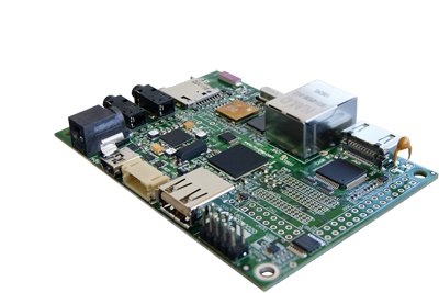
IGEP0020
|
| Overview |
| If you have successfully completed the first chapter of this guide, you can continue with this tutorial guide about IGEP0020. |
| What can I do with IGEP0020 | ||
 | ||
| 1) Booting up IGEP0020 | ||
| 2) Updating the pre-installed software | ||
| 3) Flashing the latest firmware to the IGEP0020 flash memory | ||
| 4) Connect to IGEP0020 from network interfaces | ||
| 5) Handle IGEP0020 LED's | ||
| n) Installing other distributions to IGEP0020 | ||
Booting and setting up
| Pre-installed software |
| By default, all brand new IGEP Processor Boards have a firmware installed on its flash memory.
That means that if you power up your board it will run a Linux distribution provided and installed by ISEE. |
This distribution consists on a minimal Linux-based distribution with a lite X Window System and GNOME Mobile based applications created with Poky Platform Builder.
In the previous chapter of this tutorial, we have booted IGEP0020 with its pre-installed software.
Once the board has booted up, it asks for a login in the serial debug port. You can log in into IGEP0020 via the serial interface.
*The default login user is: root
*There is no password for this user.
Boot priority
In fact, IGEP0020 can boot from many other devices (listed by priority):
- from USB
- from UART3
- from a MMC/MicroSD card
- from OneNAND memory
As we haven't set any other device rather than the oneNAND (the IGEP0020 flash memory) the system boots from it.
But, as the MicroSD card has an upper priority than the flash, if you plug a MicroSD card (with the right configuration on it) to the MicroSD card reader, IGEP0020 will boot from it and won't boot from the flash memory.
Now, We are going to use this functionality to update your pre-installed software.
Updating IGEP0020 pre-installed software
| Requirements - Overview |
For this purpose, you will need:
|
| 1) Download the latest firmware into an external computer.
2) Uncompress the downloaded file. 3) Create a MicroSD card in your external computer. 4) Plug the MicroSD card to IGEP0020 and boot from it. |
We are now going to update the pre-installed software to the latest version.
(if you are familiar with Linux, there might be some instructions and comments you can ignore, as they are for Linux newbies)
1) Downloading the latest firmware
The first thing you'll need to do is to download the latest firwmare from ISEE.
At your Linux host PC you should open Terminal and type the following command:
wget http://downloads.igep.es/binaries/firmware/poky-firmware-3.3.1-10.tar.gz
2) Uncompressing the downloaded file
Now you have donwloaded a compressed file with the latest official firmware into the current directory (.tar.gz).
Next, we will use the application 'tar' to untar (uncompress) the donwloaded file. In the same Terminal session, type:
tar xzf poky-firmware-3.3.1-10.tar.gz
Next, you can go into the extracted directory with the system 'cd' instruction:
cd poky-firmware-3.3.1-10/
3) Create a MicroSD card
We are going to create the MicroSD card with the latest firmware. Before it, you have to know which 'device' is the MicroSD listed in the /dev/ directory, a directory where the detected devices are listed by the Linux system.
To know the device name, follow this instructions:
Insert your MicroSD card into the Linux host machine (the machine where you have downloaded the firmware).
In your Terminal session, run the following system command:
dmesg
This instruction will prompt all the system traces. If your MicroSD card has actually been detected by the system, the last lines of that prompt will correspond to the MicroSD card detection and mounting.
Check the MicroSD name and path, for example: /dev/sdb and remember it.
Now you can run the following script in the folder you have just extracted, and you will have to add some parameters. In your Terminal session, type:
./poky-media-create --mmc [device] --binary poky-image-sato-igep00x0-[timestamp].tar.gz --machine igep0020
where:
- [device] is the SD card device name, for example: /dev/sdb
- [timestamp] the parameter --binary is actually the name of another .tar.gz compressed file that you have already extracted in the previous steps. If you want to auto-complete the [timestamp] parameter, press TAB in the timestamp when writing the instruction and the system will write the name of the file automatically.
This instruction will last a few minutes. When the process ends, you will have a MicroSD card with the latest software on it.
4) Plug the MicroSD card
Therefore, you are ready to try it. Plug the MicroSD card into IGEP0020 and power up your board.
Flashing the software image
Now your IGEP0020 has the latest firmware running from MicroSD card.
But you might want to write the firmware to the flash memory, so you won't need the MicroSD card when booting the board. So let's do it.
Note: The following process is assuming that your host PC is connected to IGEP0020 via the Serial Debug port. If not, read the Serial Port instructions in the previous chapter of this tutorial.
Enter to IGEP0020 using:
* root as login name
* an empty password
The software provided by ISEE has a script that flashes the content of your MicroSD Card to the flash memory in your IGEP0020.
You have to run this script, that is located at /opt/firmware directory. Open a Terminal and run:
cd /opt/firmware
./flash.sh
This will last a few minutes. When it is ready, unplug the SD card from IGEP0020 and reboot the board:
reboot
Enjoy the new firmware running from flash memory.
Other references: update your pre-installed software image
Connect to IGEP0020 via Network interfaces
| Overview |
| 1) Plug an ethernet cable to IGEP0020
2) Connect via ethernet network, SSH: root@192.168.x.x 3) Connect via wireless network, SSH: IGEP_WLAN at root@192.168.x.x |
You can log into IGEP0020 via many interfaces with network connectivity, such ethernet, wifi, usb-ethernet gadget, etc.
In this tutorial we are going to connect via an ethernet cable. To to that, you need to set an IP in IGEP0020 and start a SSH session in your host PC. Let's do it.
First of all, you will need:
- an Ethernet cable
- a Linux or a Windows host PC
Log into IGEP0020 via the serial cable to the serial debug port in IGEP0020, as you have done in the previous chapter of this tutorial guide.
Once you are logged in, run the following command:
ifconfig
This will list all the enabled network interfaces in your IGEP0020.
We are going to focus on 'eth0'. This is the ethernet interface in your IGEP0020, which is the interface we will connect to from our host PC.
Connect the ethernet cable between your host PC and IGEP0020 (or through any wired network such switch).
Now, let's set an static IP to this interface in IGEP0020, so we will be able to reach the target from the PC.
Type the following command in your serial console:
ifconfig eth0 192.168.6.2
Next, set an IP within the subnet in your host PC, for example: 192.168.6.3
Then, run a SSH client such Putty and start a SSH session to the target from your host PC.
You can download it from its official page at: http://www.chiark.greenend.org.uk/~sgtatham/putty/download.html
Install and run Putty. It will look like this:

- Select the SSH at connection type.
- Next insert the IP address of the target. In this case, the IGEP0020 IP you have already set (192.168.6.3).
- Ensure that the port is set to 22, the default for SSH communications.
- Finally, push the Open button to start the SSH session.
If everything goes right, you will be able to access to an IGEP0020 console from your host PC via ethernet.
Basic instructions in Linux
(Work in progress article. Coming soon!)
How to handle the gpio-LED's
| Overview |
| Use of IGEP0020 LED's using the associated platform device at /sys/devices/platform/leds-gpio/leds/ |
IGEP0020 has many devices that can be controlled using simple instructions.
In this tutorial, we are going to use the 4 LED's available in the board, which probably is the most simple feature in the board, but sometimes you may want LED's to be a way of checking the status of some of your applications.
You can easily turn LED's on and off using the 'echo' instruction.
Log into IGEP0020 (via serial port or via SSH, as shown before), and run the following commands to turn LED's on:
echo 1 > /sys/devices/platform/leds-gpio/leds/d240\:green/brightness
echo 1 > /sys/devices/platform/leds-gpio/leds/d240\:red/brightness
echo 1 > /sys/devices/platform/leds-gpio/leds/d440\:green/brightness
echo 1 > /sys/devices/platform/leds-gpio/leds/d440\:red/brightness
You can turn them down using the same command and write '0' instead of '1'.
Other functionalities
If you want to trigger the leds you can enable this mode and select the trigger source (none by default) to: mmc0, mmc1, timer, heartbeat and default-on.
To enable any of this modes you just have to change a parameter in the directory of the led you want to control. You can see all the possibilities using the instruction 'cat':
$   cat /sys/devices/platform/leds-gpio/leds/d240\:green/trigger

[none] mmc0 mmc1 timer heartbeat default-on
In the example above, we have checked the status of the trigger in led D240:green. Mode 'none' is selected.
To change it, for example, to the timer mode you can use 'echo':
echo timer > /sys/devices/platform/leds-gpio/leds/d240\:green/trigger
In this case, we have set the trigger to the 'timer' mode. Now you can set the time for what the led is ON and the time it is OFF using:
echo 250 > /sys/devices/platform/leds-gpio/leds/d240\:green/delay_on
echo 750 > /sys/devices/platform/leds-gpio/leds/d240\:green/delay_off
Now the selected led is configured with a timer consisting of 250 miliseconds ON and 750 miliseconds OFF.
Transfer a file to the board via network
(Work in progress article. Coming soon!)
Mounting the MicroSD Card
(Work in progress article. Coming soon!)
How to use RS-485
| Overview |
| Follow the link to the extensive article: How to use RS-485 on IGEP0020 board |
How to get sound out (audio out)
| Overview |
| Use: aplay sample.wav |
The amplifiers for the headset output are disabled by default, so the first thing you'll do is enable these amplifiers with
amixer set -D hw:0 'Headset' 0dB
amixer set -D hw:0 'HeadsetL Mixer AudioL2' on
amixer set -D hw:0 'HeadsetR Mixer AudioR2' on
Then you can easily play a wav sound, for example
aplay sample.wav
How to get sound in (audio in)
| Overview |
| Use: arecord -t wav -c 2 -r 44100 -f S16_LE -v audio-in.wav |
You can record audio in with
arecord -t wav -c 2 -r 44100 -f S16_LE -v audio-in.wav
Following output is expected on console
Recording WAVE 'audio-in.wav' : Signed 16 bit Little Endian, Rate 44100 Hz, Stereo
Plug PCM: Hardware PCM card 0 'TWL4030' device 0 subdevice 0
Its setup is:
stream       : CAPTURE
access       : RW_INTERLEAVED
format       : S16_LE
subformat    : STD
channels     : 2
rate         : 44100
exact rate   : 44100 (44100/1)
msbits       : 16
buffer_size  : 32768
period_size  : 2048
period_time  : 46439
tick_time    : 7812
tstamp_mode  : NONE
period_step  : 1
sleep_min    : 0
avail_min    : 2048
xfer_align   : 2048
start_threshold  : 1
stop_threshold   : 32768
silence_threshold: 0
silence_size : 0
boundary     : 1073741824
When ever you think you want to stop just press CONTRL+C
Developing under IGEP Technology
Visit the following link and start developing under IGEP Technology
- Cross compiling (hello world program)
- SDK tools
- Linux distributions
- Mux configuration
- Kernel modules
- Run at startup applications
- The main components of the preinstalled software of your IGEP0020:
- Bootloaders
- Kernel
- Root File System
- Kernel Modules