


User:Pau pajuelo
From IGEP - ISEE Wiki
TODO:
Update peripheral tutorials, finish gpio example program
Categorize new tutorials
Finish tutorials below
Upgrade IGEP Technology Devices Guides
Link all development tools documentation when possible (do a diagram)
How to manage the kernel modules on Linux
How do I edit my kernel command line
Basic Software instructions
What can I do with IGEP PARIS
Getting started with IGEP BERLIN
|
|
Contents
- 1 TODO:
- 2 What can I do with IGEP PARIS
- 3 Getting started with IGEP BERLIN
- 4 Overview
- 5 Requirements
- 6 Getting started
- 6.1 TFT and Touchscreen
- 6.2 Serial port
- 6.3 Ethernet Network cable
- 6.4 USB devices
- 6.5 Composite Video Decoder
- 6.6 GSM/GPRS modem
- 6.7 CAN bus
- 6.8 DVI monitor
- 6.9 VGA monitor
- 6.10 Battery
- 6.11 Connect IGEP BERLIN Expansion with IGEP COM MODULE/NEUTRON Board
- 6.12 Connect IGEP BERLIN Expansion with IGEP COM PROTON Board
- 6.13 Power up IGEP BERLIN Expansion
- 6.14 Test the Demo software distribution with touch screen
- 6.15 Log into IGEP BERLIN Expansion via Ethernet interface
- 7 [IGEP Technology devices features table proposal]
- 8 igep.ini parameters
- 9 How to use GPIOs (update it)
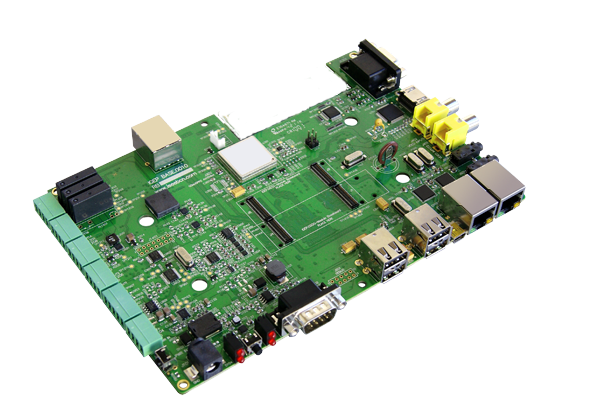
Overview
This is the 1/3 chapter of IGEP BERLIN Expansion Tutorial Guide.
In this first chapter, we will learn how to connect some expansion peripherals.
Requirements
In these tutorials we are going to need the following components:
- IGEP COM PROTON or IGEP COM MODULE.
- 5V DC power supply with a minimum of 3A current capacity.
- Seiko 7" screen if you need a touch screen.
- Ethernet cable for network communications.
- A monitor compatible with DVI-D.
- An USB keyboard and a mouse (optional).
- 4 pin connector for CAN Bus with another IGEP Board with CAN peripheral to follow CAN Bus communication tutorial.
- SIM card with an antenna to follow Telit modem tutorial.
- Composite video cable, composite video output peripheral (PAL or NTSC) and a screen to follow TVP5151 tutorial.
- Li-on battery with 3V3 (optional).
- A PC.
Getting started
TFT and Touchscreen
IGEP BERLIN Expansion supports SEIKO 7” LCD screen. Use J200, J203 and J204 connectors to attach screen. See image for more details.Know more
IGEP BERLIN Expansion integrates LCD backlight driver (TPS61081) and touch screen controller (TSC2046), a 4-wire touch screen controller which supports a low voltage I/O interface from 1.5V to 5.25V.
Serial port
Basic
IGEP BERLIN Expansion integrates a DB9 RS232 connector.
Know more
This peripheral (UART 3) can be used to debug system using kernel traces, getting a remote prompt, etc.
Ethernet Network cable
Basic
Plug an Ethernet cable between IGEP PARIS and your client machine (or any other network device with ethernet connectivity).
Know more
IGEP PARIS comes with one 10/100BASE-TX Ethernet ports.
In the following chapters we will use ethernet to access IGEP PARIS.
USB devices
Basic
Plug an USB keyboard and USB mouse to the USB ports.
Know more
Only USB 2.0 devices will work in IGEP PARIS, so if you connect any USB mouse 1.0 into the USB host connector without using a USB hub 2.0, it will not work.
Composite Video Decoder
Basic

Know more
Analog input is decoded by TVP5151.
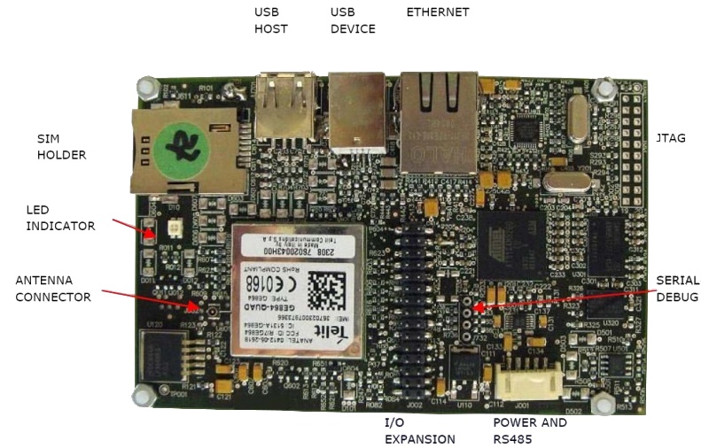
GSM/GPRS modem
Basic

|
 |
| GSM-GPRS antenna (highly recommended) | SIM card reader |
IGEPv2 Expansion integrates a GSM/GPRS modem to make phone calls or to send SMS or to write and read data from it, etc.
Know more
Modem chip Telit GE865 is a small GSM/GPRS Ball-Grid-Array BGA module with next main features:
- Quad-band EGSM 850 / 900 / 1800 / 1900 MHz
- Power consumption (typical values)
- Power off: ‹ 62 uA
- Idle (registered, power saving): 1.6 mA @ DRX=9
CAN bus
Basic

Know more
This output is controled by MICROCHIP MCP2515. J703 is a 3.5 mm pitch terminal blocks 4 Positions:
| Signal Name | Pin # |
Description |
| VDD_CAN | J703:1 | Supply Voltage (+5V DC) |
| CANL | J703:2 | CAN Low-Level Voltage I/O |
| GND | J703:3 | Ground |
| CANH | J703:4 | CAN High-Level Voltage I/O |
DVI monitor
Basic

IGEPv2 has a HDMI connector with a DVI-D interface
Connect IGEPv2 to a DVI-D compatible monitor.
Know more
The Digital Visual Interface (DVI) is a video standard interface designed to provide very high visual quality on digital display devices such as flat panel LCD computer displays and digital projectors. It is partially compatible with the High-Definition Multimedia Interface (HDMI) standard in digital mode (DVI-D), and VGA in analog mode (DVI-A).
Note that your monitor should be able to support 1024 x 768 @ 60 Hz, which is the default resolution in the preinstalled software.
VGA monitor

Basic
IGEPv2 Expansion integrates a VGA connector, the output VGA signal is equal to HDMI connector. Plug a monitor with VGA input.
Know more
This output is controled by ADV7125KSTZ140 Integrated Circuit.
Battery

J102 is a 2.5mm pitch, can be used to connect a 3,7V Battery to power the base board.
Connect IGEP BERLIN Expansion with IGEP COM MODULE/NEUTRON Board

The IGEP BERLIN Expansion connects to the IGEP COM MODULE/NEUTRON Board through J1 and J4 connectors. Just take a look on the figure below to mount it:
Connect IGEP BERLIN Expansion with IGEP COM PROTON Board

The IGEP BERLIN Expansion connects to the IGEP COM PROTON Board through J1, J4, J9 and J8 connectors. Just take a look on the figure below to mount it:
Power up IGEP BERLIN Expansion

Once you have connected the peripherals you can apply power to your IGEP BERLIN with 5V DC power supply (J101) with a minimum of 3A current capacity.
Test the Demo software distribution with touch screen
Basic
When IGEP BERLIN powers up, the desktop of the preinstalled software will appear on the touch screen.
You can use your fingers to test the demo applications.

Know more
All IGEP Processor Boards have a pre-installed software in its flash memory which consists of a minimal Linux-based distribution with a lite X Window System and GNOME Mobile based applications created with Poky Platform Builder.
Log into IGEP BERLIN Expansion via Ethernet interface

|
In non-Linux operating system, use IGEP SDK Virtual Machine to connect to IGEP COM MODULE via USB or read article "Using USB ethernet gadget to communicate" |
In your Host Machine:
Open a Terminal session and set the IP of the Ethernet interface in which IGEP is connected (for example eth0):
- In the file /etc/network/interfaces, you should add:
iface eth0 inet dhcp
iface eth0:0 inet static
address 192.168.5.10
netmask 255.255.255.0
- Type in a terminal:
sudo ifup eth0:0
- Revise that:
jdoe@ubuntu ~ $ ifconfig
...
eth0:0    Link encap:Ethernet  HWaddr 08:00:27:ad:0c:ad
          inet addr:192.168.5.10  Bcast:0.0.0.0  Mask:255.255.255.0
          UP BROADCAST RUNNING MULTICAST  MTU:1500  Metric:1
...
- Connect to IGEP device
jdoe@ubuntu ~ $ ssh root@192.168.5.1
You have successfully completed this chapter of the guide.
|

|
If you have any question, don't ask to ask at the IGEP Community Forum or the IGEP Community Chat | 
|
|
|
[IGEP Technology devices features table proposal]
| IGEP0032 | IGEP0030 | IGEP0030 | IGEP0020 | IGEP0010 | |
| Product name | IGEP COM PROTON | IGEP COM MODULE | IGEP COM ELECTRON | IGEPv2 | IGEP0010 |
 |
 |
 |
 |
 | |
| Devices and interfaces | (discontinued product) | ||||
| ARM CPU | DM3730 1GHz | DM3730 1GHz | AM3703 1GHz | DM3730 1GHz | - |
| DSP | TMS320DM-C64+ 800 Mhz | TMS320DM-C64+ 800 Mhz | - | TMS320DM-C64+ 800 Mhz | - |
| RAM Memory | 512 MBytes / 200 Mhz | 512 MBytes / 200 Mhz | 256 MBytes / 200 Mhz | 512 MBytes / 200 Mhz | - |
| Flash Memory | 512 MBytes | 512 MBytes | 512 MBytes | 512 MBytes | - |
| MicroSD Card Reader | x 1 | x 1 | x 1 | x 1 | - |
| USB 2.0 Host | - | - | - | x 1 | - |
| USB 2.0 OTG | x 1 | x 1 | x 1 | x 1 | - |
| RS232 | - | - | - | x 1 | - |
| RS485 | - | - | - | x 1 | - |
| JTAG | x 1 | - | - | x 1 | - |
| Stereo audio In/Out | - | - | - | x 1 | - |
| DVI on HDMI | - | - | - | x 1 | - |
| Ethernet | - | - | - | x 1 | - |
| Wifi | - | x 1 | - | x 1 | - |
| Bluetooth | - | x 1 | - | x 1 | - |
| EEPROM | x 1 | - | - | - | - |
| S-Video | - | - | - | T.P. | - |
| Camera Interface | - | x 1 | - | N.P. | - |
| Analog to digital converter | - | - | - | N.P. | - |
| Keyboard matrix | - | - | - | N.P. | - |
| LEDs | x 3 green LEDs | x 2 bicolor LEDs | x 1 bicolor LED | x 2 bicolor LEDs | - |
| TFT Interface | - | - | - | x 2 | - |
| RTC Battery Back Up | - | - | - | x 2 | - |
| Size | 35x51,2mm | 18x68,5mm | 18x68,5mm | 65x95mm | - |
| Expansion connectors | Power and many functionalities from OMAP3 processor | Power and many functionalities from OMAP3 processor | Power and many functionalities from OMAP3 processor | Power 5V and 1.8V, UART, McBSP, McSPI, I2C, GPIO, RS485 with transceiver, Keyboard | - |
| Main pages | |
|
|
|
- |
| |
|
|
| ||
| Getting started guide |
|
|
|
| |
| Hardware manual | |
|
|
|
- |
- O: Available on board
- N.P.: Not populated THESE DEVICES and/or CONNECTORS ARE AVAILABLE, BUT NOT POPULATED BY DEFAULT
- T.P.: Test points
igep.ini parameters
The kernel command line syntax is name=value1. These next parameters are supported in igep.ini since IGEP-X_Loader 2.4.0-2:
[kernel]
| Parameter Name | Description | Default value | Comments |
| kaddress | Kernel copy address | =0x80008000 | Hex memory address |
| rdaddress | Ram Disk location address | =0x81600000 | Hex memory address; disabled by default |
| serial.low | Serial number (low part) | =00000001 | Numeric |
| serial.high | Serial number (high part) | =00000000 | Numeric |
| revision | Revision ID | =0003 | Numeric |
| kImageName | Kernel, binary image name | =zImage | Kernel or binary image name |
| kRdImageName | Kernel RAM Disk Image Name | - | Ram Disk image name |
| MachineID | Machine ID (kernel ID) | ;IGEPv2 =2344 |
;Module =2717 ;Proton =3203 |
| Mode | Boot Mode | ;Linux kernel =kernel |
;Other image (like uboot) [binary image] |
[kparams]
| Parameter Name | Description | Default value | Comments |
| buddy | Enable/disable expansion board support | ;IGEPv2 Expansion Board support =igep0022 |
;Berlin and Paris Expansion Board support =base0010 New York Expansion =ilms0015 |
| console | Setup the kernel console parameters | =ttyO2,115200n8 | - |
| earlyprintk | Enable early printk | - | - |
| mem | Setup the Board Memory Configuration | =430M | - |
| boot_delay | Setup the boot delay | =0 | - |
| mpurate | Setup ARM Processor Speed | - | - |
| loglevel | Setup the loglevel | - | - |
| debug | Enable kernel debug output | - | - |
| fixrtc | Fix RTC variable | - | - |
| nocompcache | Configure nocompcache variable | =1 | - |
| omapfb.mode | Configure frame bugger configuration | =dvi:hd720-16@50 | ;Other configuration =dvi:1280x720MR-16@60 |
| vram | Configure Video RAM assigned to every frame buffer | - | - |
| omapfb.vram | Configure Video RAM assigned to every frame buffer | - | - |
| omapfb.debug | Configure frame buffer debug output | - | - |
| omapdss.debug | Configure DSS Video debug output | - | - |
| smsc911x.mac0 | Configure Board Ethernet Mac Address | =0xb2,0xb0,0x14,0xb5,0xcd,0xde | For IGEP BERLIN |
| smsc911x.mac1 | Configure Board Ethernet Mac Address | =0xb2,0xb0,0x14,0xb5,0xcd,0xdf | For IGEP BERLIN (only with IGEP PROTON) |
| smsc911x.mac | Configure Board Ethernet Mac Address | =0xb2,0xb0,0x14,0xb5,0xcd,0xde | For IGEPv2, IGEP PROTON, IGEP PARIS and IGEP BERLIN |
| ubi.mtd | Fot UBI FS boot | - | - |
| root | Configure root directory for MMC, NFS or UBI | ;For mmc memory =/dev/mmcblk0p2 rw rootwait |
;For flash memory =/dev/mtdblock2 |
| nfsroot | For NFS boot | - | - |
| rootfstype | For UBI FS boot | - | - |
| ip | For NFS boot | - | - |
| init | Assign init program | - | - |
| musb_hdrc.debug | USB debug | - | - |
| musb_hdrc.use_dma | USB over network | - | - |
| libertas.libertas_debug | Configure libertas debug | - | - |
| board.ei485 | Enable/disable RS485 | ;Enable RS485 =yes |
;Disable RS485 =no |
| board.modem | Enable/disable GPRS modem | ;Enable modem (IGEPv2 Expansion) =no |
;Enable modem (IGEPv2 Expansion) =yes |
| buddy.revision | Enable hardware buddy revision [A or B] | Only for base0010 =A |
Only for base0010 =B |
How to use GPIOs (update it)
Overview
This How-To is meant to be a starting point for people to learn use GPIOs for IGEP v2 devices as quickly and easily as possible. For this how-to i used Linaro Headless with Kernel 2.6.35.y, Ubuntu 10.04 with Linaro Toolchain, IGEP v2 RC5 and GPIO driver.
There are more ways to use GPIOs in IGEP v2, but this one is very simple.
Feedback and Contributing
At any point, if you see a mistake you can contribute to this How-To.
Compile GPIO driver source code via Host
Download GPIO driver and Kernel 2.6.35.y source code. Extract files.
Edit GPIO driver Makefile's:
-In files: $/app/Makefile and $/lib/Makefile, make sure that your CROSS_COMPILE path is correct.
-In file: $/modules/Makefile, make sure that your CROSS_COMPILE path is correct and type your Kernel 2.6.35.y path.
We will use the ncurses program for set up Kernel configuration, if you don't have this program installed then you must install it with this command:
sudo apt-get install ncurses-dev
-Go to kernel path and type:
make ARCH=arm CROSS_COMPILE=arm-linux-gnueabi- igep00x0_defconfig
Exit Linux Kernel Configuration an return to Bash. Type:
make ARCH=arm CROSS_COMPILE=arm-linux-gnueabi- modules_prepare
File $/include/generated/autoconf.h was created
Finally compile GPIO driver, go to main Makefile path and compile all source code using make command.
Send binaries created from Host to Igep v2.
Install binaries via IGEP
Log with root user to install binaries.
Install module
Go to:$/modules and insert user-gpio-drv.ko into linux kernel with the following command:
insmod user-gpio-drv.ko
Check that user-gpio-drv.ko is currently loaded with the following command:
lsmod
The result will be similar at that:
root@localhost:~/gpio-driver/module# lsmod
Module                  Size  Used by
user_gpio_drv           1639  0
omap_wdt                3411  0
spidev                  4198  0
iommu                   8558  0
rtc_twl                 4411  0
rtc_core               11187  1 rtc_twl
twl4030_keypad          2970  0
The module is loaded until system halt.
Go to:$/lib. libgpio.so is here.
If a program is linked with shared libraries, Kernel seek in specific paths when program is executed. Now is necessary link the libgpio.so path to the environment variable LD_LIBRARY_PATH, use the following command:
export LD_LIBRARY_PATH=/root/gpio-driver/lib/
Check that libgpio.so is linked correctly. Go to:$/gpio-driver/app, gpio program is here. Type next command:
ldd gpio
ldd command, print shared library dependencies. The result will be similar at that:
root@localhost:~/gpio-driver/app# ldd gpio
	libgpio.so => /root/gpio-driver/lib/libgpio.so (0x40197000)
	libc.so.6 => /lib/libc.so.6 (0x401a0000)
	/lib/ld-linux.so.3 (0x4008a000)
The shared library is linked until system halt. Now you can execute gpio example program.
Testing driver
To make sure than driver works well, make the next test. I used GPIO_136(sdmmc2_dat4) and GPIO_137(sdmmc2_dat5) because IGEP v2 RC5(without WIFI) don't use them by default:
NOTE: For more information visit this page (under construction).
Configure Mux
Go to:/sys/kernel/debug/omap_mux, and change this mux configuration:
echo 0x104>sdmmc2_dat4
echo 0x104>sdmmc2_dat5
Use cat command to check it:
cat sdmmc2_dat4
cat sdmmc2_dat5
The result will be similar at that:
root@localhost:/sys/kernel/debug/omap_mux# cat sdmmc2_dat4
name: sdmmc2_dat4.gpio_136 (0x48002164/0x134 = 0x0104), b ae4, t NA
mode: OMAP_PIN_INPUT | OMAP_MUX_MODE4
signals: sdmmc2_dat4 | sdmmc2_dir_dat0 | NA | sdmmc3_dat0 | gpio_136 | NA | NA | safe_mode
and
root@localhost:/sys/kernel/debug/omap_mux# cat sdmmc2_dat5
name: sdmmc2_dat5.gpio_137 (0x48002166/0x136 = 0x0104), b ah3, t NA
mode: OMAP_PIN_INPUT | OMAP_MUX_MODE4
signals: sdmmc2_dat5 | sdmmc2_dir_dat1 | cam_global_reset | sdmmc3_dat1 | gpio_137 | hsusb3_tll_stp | mm3_rxdp | safe_mode
Note: OMAP_PIN_INPUT=Input/Output pin and OMAP_PIN_OUTPUT=Output pin, for Read/Write test you need the first one. GPIO is configured in mode 4.
Read/Write test
Link GPIO_136 and GPIO_137 with a wire, these pins are located in J990 connector with numbers 7 and 9. I use the next connector to join them:
 |
 |
Now type next code:
root@localhost:~/gpio-driver/app# ./gpio input 136
root@localhost:~/gpio-driver/app# ./gpio output 137 0
root@localhost:~/gpio-driver/app# ./gpio get 136
0
root@localhost:~/gpio-driver/app# ./gpio output 137 1
root@localhost:~/gpio-driver/app# ./gpio get 136
1
root@localhost:~/gpio-driver/app#
The results (CMOS Voltages: 0V-1V8):
 |
 |
The code above shows that driver works properly, GPIO_136 is configured like input and GPIO_137 is configured like output with value 0, when read GPIO_136 the result is 0. To make sure that works well, configure GPIO_137 with value 1, now GPIO_136 reads 1.
This driver have more options like IRQ, but is not explained here.