Difference between revisions of "User:Pau pajuelo"
From IGEP - ISEE Wiki
m (→Compile GPIO driver source code via Host) |
m (→Install binaries via IGEP) |
||
| Line 245: | Line 245: | ||
== Install binaries via IGEP<br> == | == Install binaries via IGEP<br> == | ||
| − | |||
| − | |||
| − | |||
| − | |||
| − | |||
| − | |||
| − | |||
| − | |||
| − | |||
| − | |||
| − | |||
| − | |||
| − | |||
| − | |||
| − | |||
| − | |||
| − | |||
| − | |||
| − | |||
| − | |||
| − | |||
| − | |||
| − | |||
| − | |||
| − | |||
| − | |||
| − | |||
| − | |||
| − | |||
| − | |||
| − | |||
| − | |||
| − | |||
| − | |||
| − | |||
| − | |||
| − | |||
| − | |||
| − | |||
| − | |||
== Testing driver == | == Testing driver == | ||
Revision as of 18:08, 14 September 2012
Contents
TODO:
Update peripheral tutorials, finish gpio example program
Categorize new tutorials
Finish tutorials below
How to manage the kernel modules on Linux
How do I edit my kernel command line
Basic Software instructions
igep.ini parameters
The kernel command line syntax is name=value1. These next parameters are supported in igep.ini since IGEP-X_Loader 2.4.0-2:
[kernel]
| Parameter Name | Description | Default value | Comments |
| kaddress | Kernel copy address | =0x80008000 | Hex memory address |
| rdaddress | Ram Disk location address | =0x81600000 | Hex memory address; disabled by default |
| serial.low | Serial number (low part) | =00000001 | Numeric |
| serial.high | Serial number (high part) | =00000000 | Numeric |
| revision | Revision ID | =0003 | Numeric |
| kImageName | Kernel, binary image name | =zImage | Kernel or binary image name |
| kRdImageName | Kernel RAM Disk Image Name | - | Ram Disk image name |
| MachineID | Machine ID (kernel ID) | ;IGEPv2 =2344 |
;Module =2717 ;Proton =3203 |
| Mode | Boot Mode | ;Linux kernel =kernel |
;Other image (like uboot) [binary image] |
[kparams]
| Parameter Name | Description | Default value | Comments |
| buddy | Enable/disable expansion board support | ;IGEPv2 Expansion Board support =igep0022 |
;Berlin and Paris Expansion Board support =base0010 New York Expansion =ilms0015 |
| console | Setup the kernel console parameters | =ttyO2,115200n8 | - |
| earlyprintk | Enable early printk | - | - |
| mem | Setup the Board Memory Configuration | =430M | - |
| boot_delay | Setup the boot delay | =0 | - |
| mpurate | Setup ARM Processor Speed | - | - |
| loglevel | Setup the loglevel | - | - |
| debug | Enable kernel debug output | - | - |
| fixrtc | Fix RTC variable | - | - |
| nocompcache | Configure nocompcache variable | =1 | - |
| omapfb.mode | Configure frame bugger configuration | =dvi:hd720-16@50 | ;Other configuration =dvi:1280x720MR-16@60 |
| vram | Configure Video RAM assigned to every frame buffer | - | - |
| omapfb.vram | Configure Video RAM assigned to every frame buffer | - | - |
| omapfb.debug | Configure frame buffer debug output | - | - |
| omapdss.debug | Configure DSS Video debug output | - | - |
| smsc911x.mac0 | Configure Board Ethernet Mac Address | =0xb2,0xb0,0x14,0xb5,0xcd,0xde | For IGEP BERLIN |
| smsc911x.mac1 | Configure Board Ethernet Mac Address | =0xb2,0xb0,0x14,0xb5,0xcd,0xdf | For IGEP BERLIN (only with IGEP PROTON) |
| smsc911x.mac | Configure Board Ethernet Mac Address | =0xb2,0xb0,0x14,0xb5,0xcd,0xde | For IGEPv2, IGEP PROTON, IGEP PARIS and IGEP BERLIN |
| ubi.mtd | Fot UBI FS boot | - | - |
| root | Configure root directory for MMC, NFS or UBI | ;For mmc memory =/dev/mmcblk0p2 rw rootwait |
;For flash memory =/dev/mtdblock2 |
| nfsroot | For NFS boot | - | - |
| rootfstype | For UBI FS boot | - | - |
| ip | For NFS boot | - | - |
| init | Assign init program | - | - |
| musb_hdrc.debug | USB debug | - | - |
| musb_hdrc.use_dma | USB over network | - | - |
| libertas.libertas_debug | Configure libertas debug | - | - |
| board.ei485 | Enable/disable RS485 | ;Enable RS485 =yes |
;Disable RS485 =no |
| board.modem | Enable/disable GPRS modem | ;Enable modem (IGEPv2 Expansion) =no |
;Enable modem (IGEPv2 Expansion) =yes |
| buddy.revision | Enable hardware buddy revision [A or B] | Only for base0010 =A |
Only for base0010 =B |
How to use GPIOs (update it)
Overview
This How-To is meant to be a starting point for people to learn use GPIOs for IGEP devices as quickly and easily as possible. For this how-to i used IGEP firmware Yocto
There are more ways to use GPIOs in IGEP v2, but this one is very simple.
Feedback and Contributing
At any point, if you see a mistake you can contribute to this How-To.
Install binaries via IGEP
Testing driver
To make sure than driver works well, make the next test. I used GPIO_136(sdmmc2_dat4) and GPIO_137(sdmmc2_dat5) because IGEP v2 RC5(without WIFI) don't use them by default:
NOTE: For more information visit this page (under construction).
Configure Mux
Go to:/sys/kernel/debug/omap_mux, and change this mux configuration:
echo 0x104>sdmmc2_dat4
echo 0x104>sdmmc2_dat5
Use cat command to check it:
cat sdmmc2_dat4
cat sdmmc2_dat5
The result will be similar at that:
root@localhost:/sys/kernel/debug/omap_mux# cat sdmmc2_dat4
name: sdmmc2_dat4.gpio_136 (0x48002164/0x134 = 0x0104), b ae4, t NA
mode: OMAP_PIN_INPUT | OMAP_MUX_MODE4
signals: sdmmc2_dat4 | sdmmc2_dir_dat0 | NA | sdmmc3_dat0 | gpio_136 | NA | NA | safe_mode
and
root@localhost:/sys/kernel/debug/omap_mux# cat sdmmc2_dat5
name: sdmmc2_dat5.gpio_137 (0x48002166/0x136 = 0x0104), b ah3, t NA
mode: OMAP_PIN_INPUT | OMAP_MUX_MODE4
signals: sdmmc2_dat5 | sdmmc2_dir_dat1 | cam_global_reset | sdmmc3_dat1 | gpio_137 | hsusb3_tll_stp | mm3_rxdp | safe_mode
Note: OMAP_PIN_INPUT=Input/Output pin and OMAP_PIN_OUTPUT=Output pin, for Read/Write test you need the first one. GPIO is configured in mode 4.
Read/Write test
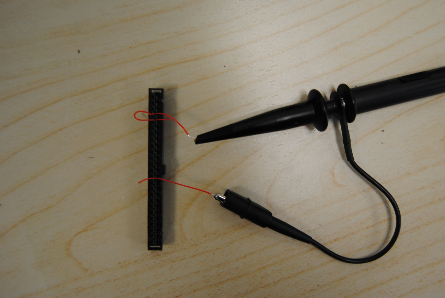
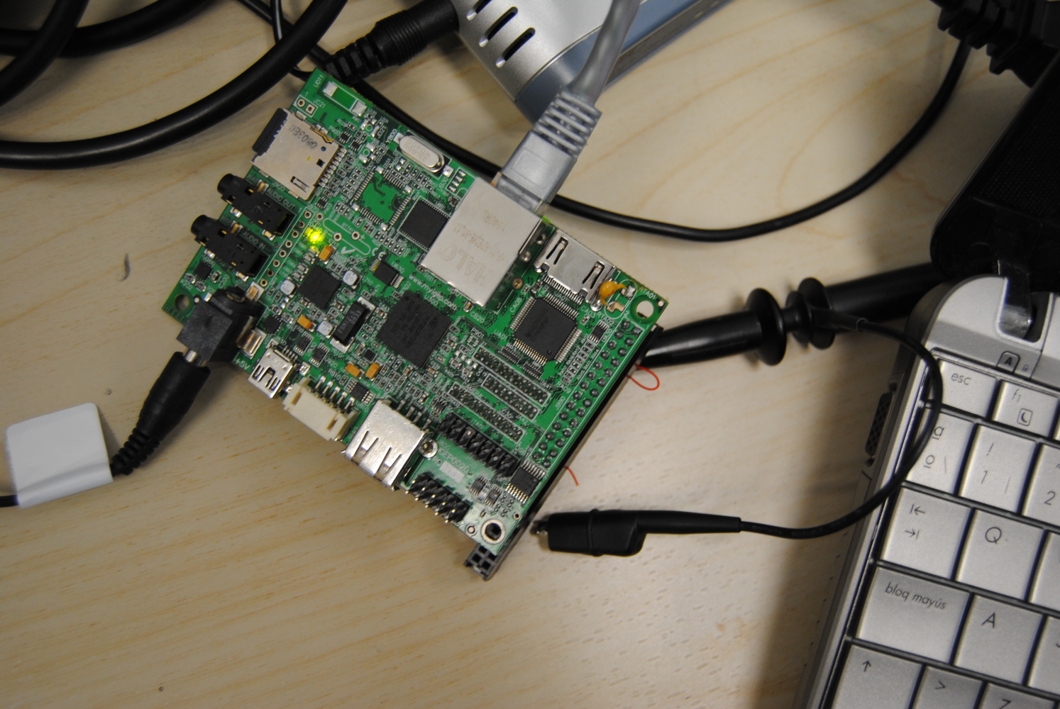
Link GPIO_136 and GPIO_137 with a wire, these pins are located in J990 connector with numbers 7 and 9. I use the next connector to join them:
Now type next code:
root@localhost:~/gpio-driver/app# ./gpio input 136
root@localhost:~/gpio-driver/app# ./gpio output 137 0
root@localhost:~/gpio-driver/app# ./gpio get 136
0
root@localhost:~/gpio-driver/app# ./gpio output 137 1
root@localhost:~/gpio-driver/app# ./gpio get 136
1
root@localhost:~/gpio-driver/app#
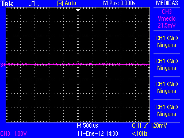
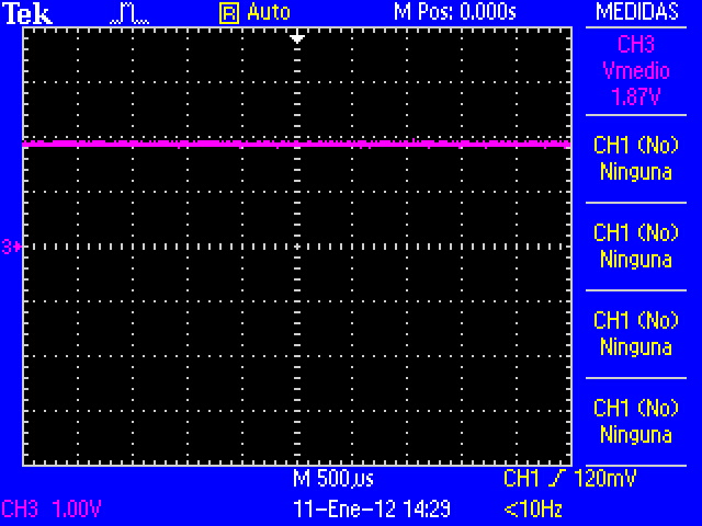
The results (CMOS Voltages: 0V-1V8):
The code above shows that driver works properly, GPIO_136 is configured like input and GPIO_137 is configured like output with value 0, when read GPIO_136 the result is 0. To make sure that works well, configure GPIO_137 with value 1, now GPIO_136 reads 1.
This driver have more options like IRQ, but is not explained here.


