How to use UARTs
From IGEP - ISEE Wiki
Overview
This How-To is meant to be a starting point for people to learn use UART for IGEP devices as quickly and easily as possible. In this how-to, we use IGEP Firmware and a program that use UART peripherals. This How-to was tested in:
Example program has a debug option using GPIOs to debug via oscilloscope, this method is useful to learn about the Kernel latencies. Debug has set to "write" and "select" functions. More information.
Preparing IGEP
Configure UART1 and UART3 in IGEP with RS232 levels on J960 connector
Edit igep.ini file
To test UARTs we use UART1 (dev/ttyO0) and UART3 (dev/ttyO2) via J960 connector using RS232 standard.
- UART1 can used by RS485 driver, we need to disable it, edit igep.ini file:
board.ei485= yes
- UART1 is configured in RS232 driver, when igep line is replaced by (or type in -Maybe you don't found this line-):
board.ei485= no
- By default, UART3 is used by Kernel serial console, we need to disable it, go to igep.ini file, comment next line:
;console=ttyO2,115200n8
;console=ttyO
Edit inittab file
Getty program uses /dev/ttyO2 in IGEP Firmware, disable it modifying /dev/inittab file:
- Comment next line:
#S:2345:respawn:/sbin/getty 115200 ttyO2
Check UARTs devices
Make sure that Kernel detects UARTs, type:
dmesg | grep tty
The result will be similar at that:
root@igep00x0:~# dmesg | grep tty
[    0.000000] console [tty0] enabled
[    0.485198] omap_uart.0: ttyO0 at MMIO 0x4806a000 (irq = 72) is a OMAP UART0
[    0.485565] omap_uart.1: ttyO1 at MMIO 0x4806c000 (irq = 73) is a OMAP UART1
[    0.485931] omap_uart.2: ttyO2 at MMIO 0x49020000 (irq = 74) is a OMAP UART2
[    0.486267] omap_uart.3: ttyO3 at MMIO 0x49042000 (irq = 80) is a OMAP UART3
root@igep00x0:~#
Connect peripherals
Connect IGEPv2 board using J960 connector like this:
 J960
                  ------
    (Not used) x---| 1  2 |---o (Connect to 8)
(Connect to 9) o---| 3  4 |---x (Not used)
         (GND)·|---| 5  6 |---|· (GND)
     (Not used)x---| 7  8 |---o (Connect to 2)
(Connect to 3) o---| 9 10 |---x (Not used)
                  ------
Send some data
Use microcom to prove it, open two terminals via SSH and log with root user:
Terminal 1:
microcom /dev/ttyO0
Terminal 2:
microcom /dev/ttyO2
Type something in one terminal.
Schematics
RS232 Schematic Igep V2
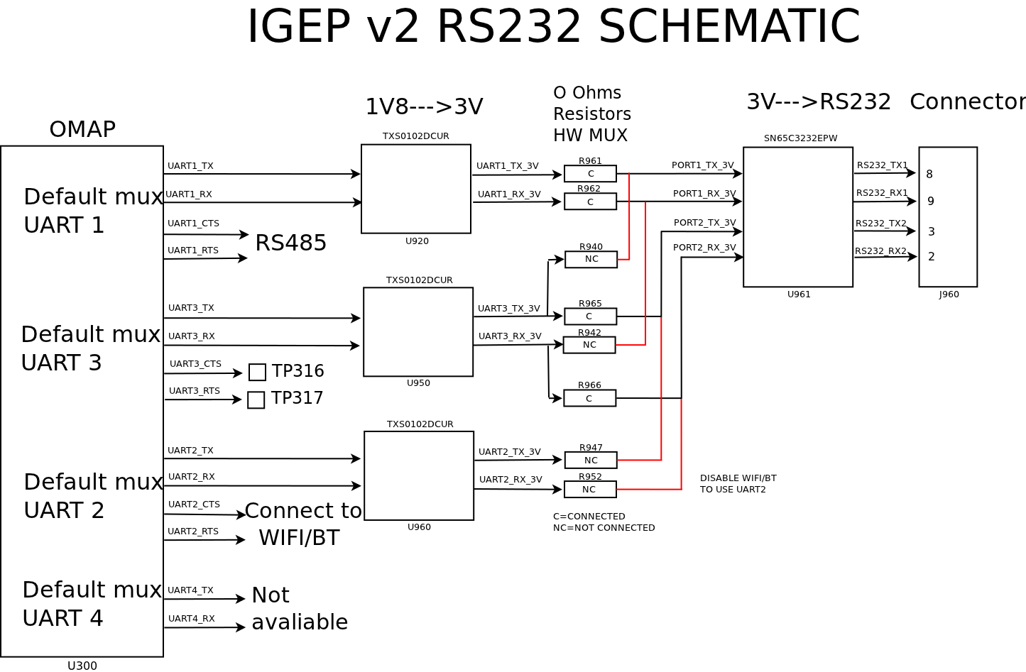
|
Uart Schematic Igep Module
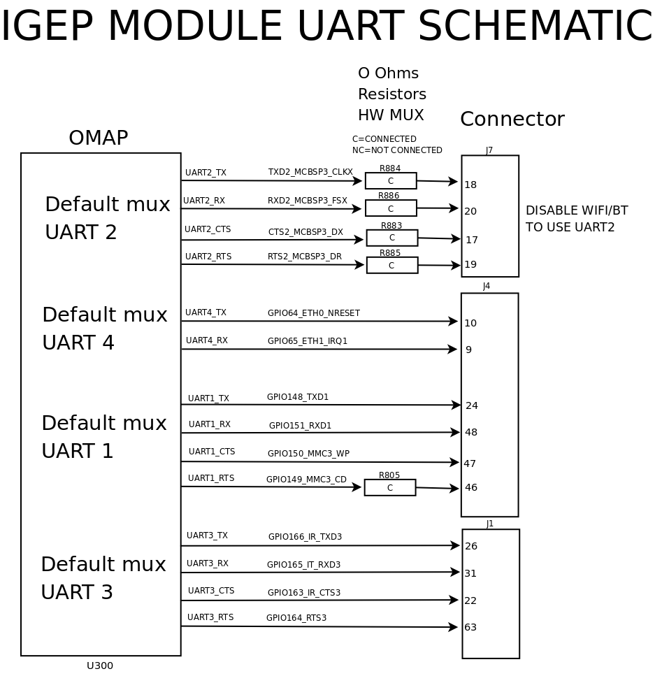
|
Compile and run program
Download program source and extract it. Before compiling the program, there are some interesting things to configure. Open program and seek next lines:
//Define Array char size
#define SIZE 30

//Define Debug mode:0==Disable
#define DEBUG 0

//Define wait select
#define WAIT 5

//Set GPIO Debugger port
//Be sure that mux is correctly configured and GPIOs are not used
#define GPIO1 158
#define GPIO2 162
Constant SIZE: it determines the max number of chars sended.
Constant DEBUG: it can break program infinite loop part, useful to debug errors: 0 (infinite loop) or positive number determines loop max entrances.
Constant WAIT: it configures select max time in seconds.
Constants GPIO1 and GPIO2: they configure GPIOs used for debug via oscilloscope. By default, 158 and 162 values are not used in IGEPv2. Configure mux properly if you use other GPIOs.
Compile source code using a cross compiler for example IGEP SDK:
arm-poky-linux-gnueabi-gcc uart-test-2-beta1.c -o uart-test-beta1
Testing UART
Some tests do it:
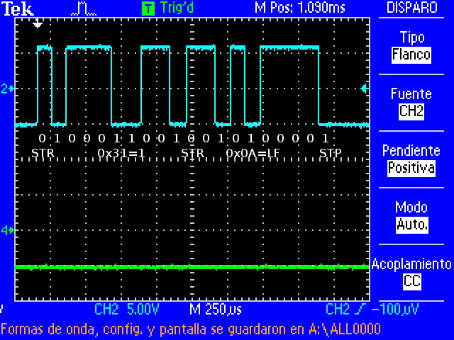
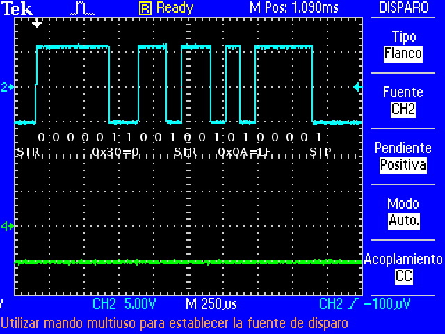
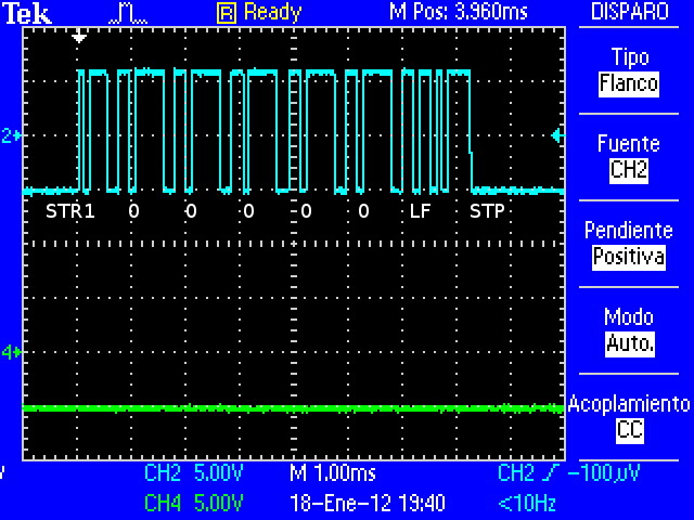
Decode Characters
Decoded with ASCII table.
|
|
|
| Decoding "1\n" | Decoding "0\n" | Decoding "100000\n" |
Click to enlarge image
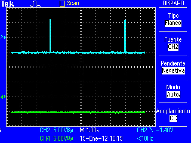
select timeout
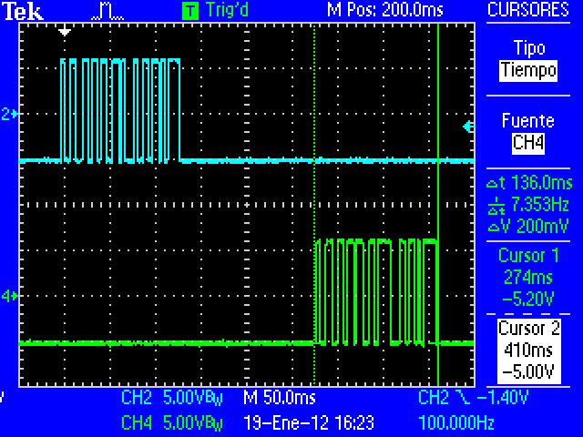
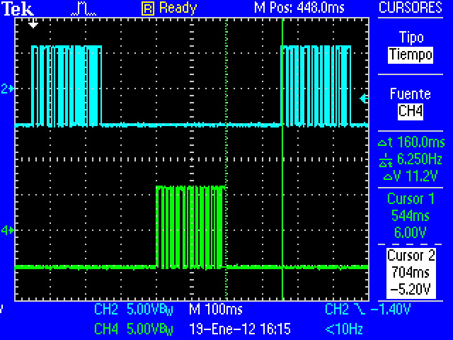
Program sends information via UART1 but don't receive response via UART3, because only a process is executed. This problem is repeated every 5 seconds (constant WAIT=5) until other process sends information via UART3 at the same speed. If "select" hasn't been implemented, process would have stayed blocked.
|
| UART1=Blue and UART3=Green |
Click to enlarge image
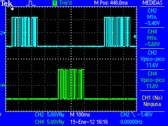
RS232 Voltage params
More information here.
|
| Vpp=11.8V aprox , Vmin=-5.6V aprox |
Click to enlarge image
Speed Overview
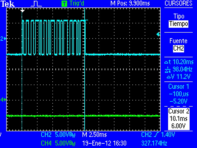
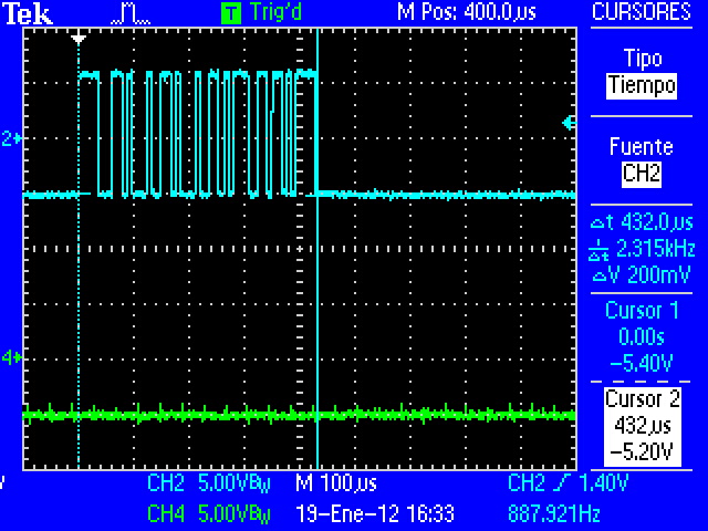
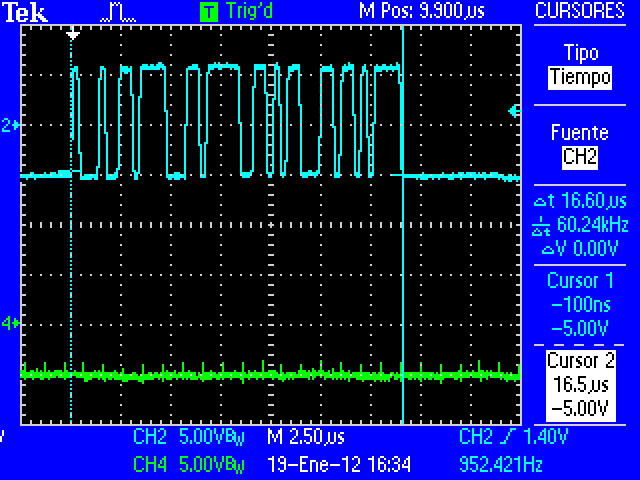
Note that wave is degraded when speed is higher
Click to enlarge image
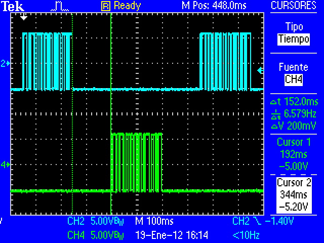
Lag
You can see that RS232 have some lag between transmisions. This caused mainly by kernel process management. UART peripheral is controlled by Linux and It isn't a real-time operating system.
|
 select: blocked until all data is available. select: blocked until all data is available.
|
| Lag between UART1 and UART3 (300 bauds) | Lag between UART3 and UART1 (300 bauds) |
Click to enlarge image
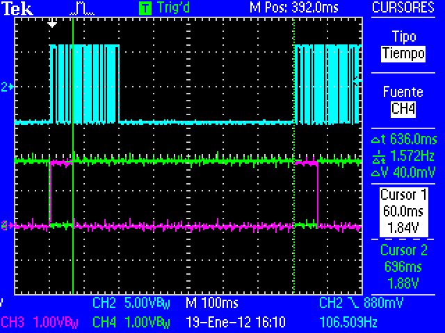
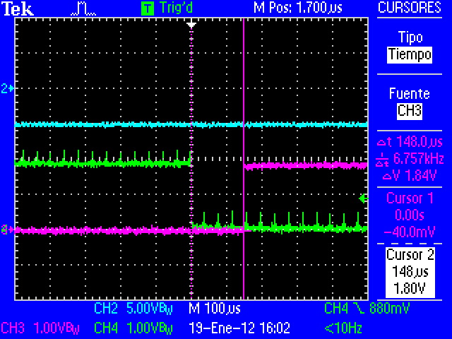
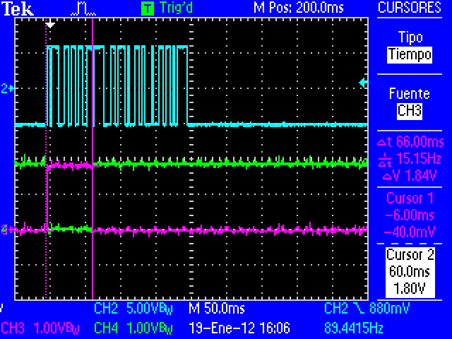
This program have three I/O functions that connect to UART driver via ioctl: (read(), write() and select()). But select() and write() change process stat to sleep mode until system don't receive or transmit all information via UART. "select" function is used to prevent that read function can be blocked when data aren't available.
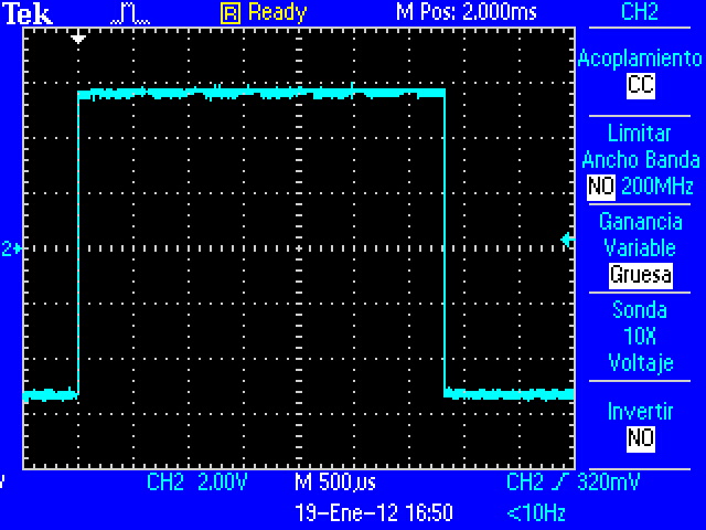
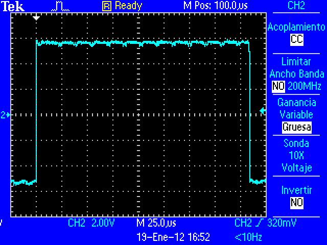
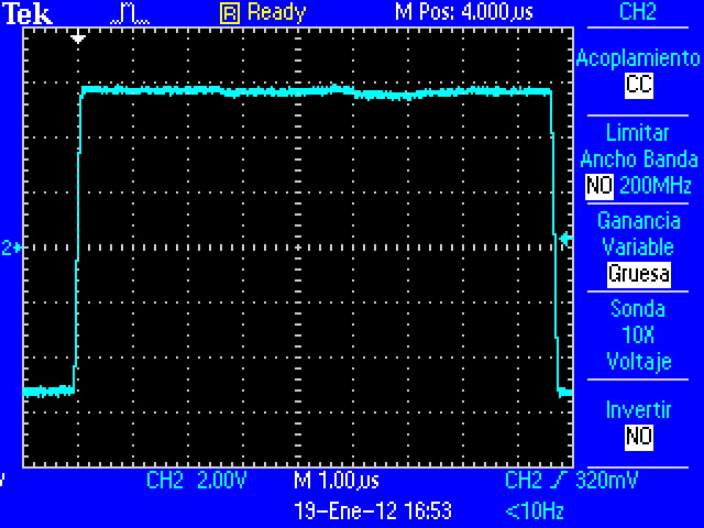
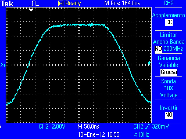
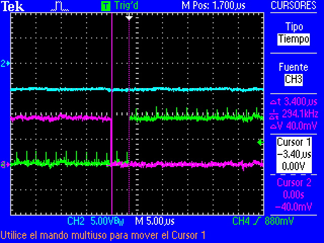
The next images (program with debug_gpio enabled and 300 bauds speed) show when process is executed or is waiting. Blue=UART1, Violet="write" and Green="select". When GPIO has HIGH value, process is blocked.
|
|
|
|
| select function time | Time between select and write | write function time | Time between write and select |
Click to enlarge image
In this case:
select: blocked until all data is available (LF char received).
write: blocked until all data is send to UART buffer.
Error test
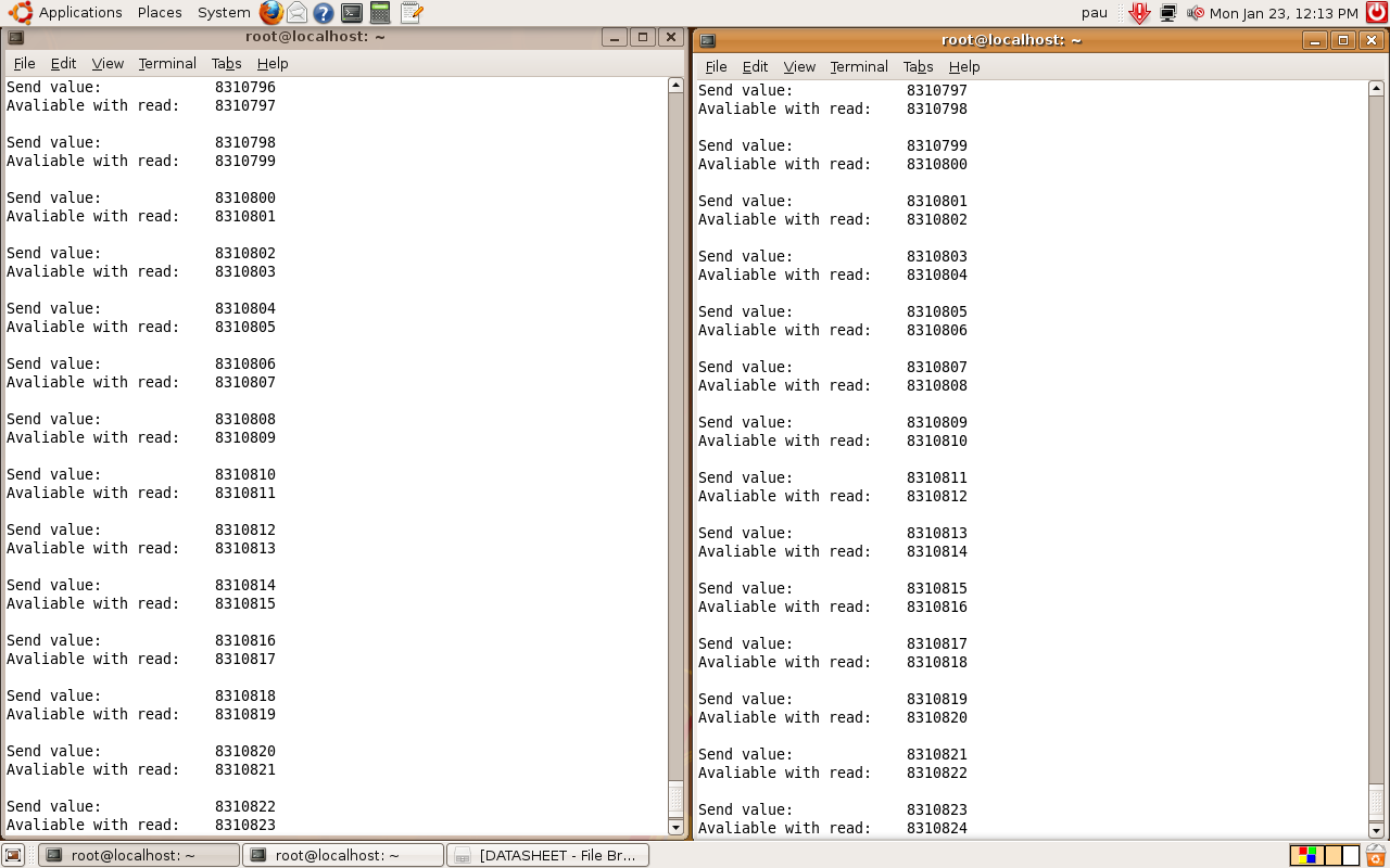
Every full process the number is increased twice. Program checks that this condicion is true, if it isn't accomplished, process will be finish.
|
| Runs 16h without any transfer error (3000000 bauds) |


