


Getting started with IGEP RADAR SENSOR ORION
From IGEP - ISEE Wiki
|
|
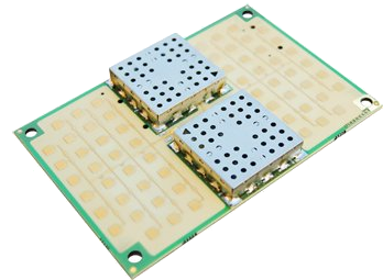
Identify the different parts of the radar sensor ORION
It is very important you are able to identify the basic parts of the radar in order to avoid wrong set ups of measurement.
The next picture show which is the 24GHz transmitting antenna, the receiving antenna, the transmitter (TX) and the receiver (RX):

You can also take a look at the bottom face:

JL1 gives you access to the VCO signal
JD1 is the modulation signal
JD2 is the synchronism (you can use this signal to visualise the others on an oscilloscope)
JF1 is the IF signal
JC2 is the expansion connector for IGEPv2
JC4 and JC3 are the expansion connectors for IGEP COM MODULE
JP1 is the power connector
You have successfully completed this chapter of the guide.
|

|
If you have any question, don't ask to ask at the IGEP Community Forum or the IGEP Community Chat | 
|