


Getting started with IGEP COM AQUILA
From IGEP - ISEE Wiki
| |
| |||||||||
| |
This is a work in progress article. Help other developers like you in the IGEP Community by improving it! |
Overview
This is the 1/3 chapter of the Getting Started with IGEP COM AQUILA Tutorial Guide.
The first chapter helps to develop a baseboard that lets us expand the IGEP COM AQUILA functionalities.
Upon completion, you will be ready to continue with chapter 2/3 that explains how to use templates, tools and other methods to help us create a custom Linux-based system for your project.

|
This chapter is based in some references detailed below. Read this references or ask to forum if this guide doesn't resolve your dudes. |
Resources
Main Resources
For this tutorial, we are going to use some resources available into IGEP COM AQUILA MainPage and IGEP AQUILA EXPANSION MainPage.
- IGEP COM AQUILA Hardware Reference Manual
- IGEP AQUILA EXPANSION Hardware Reference Manual
- IGEP AQUILA EXPANSION Public Schematics
- IGEP AQUILA EXPANSION Mechanical Layout PCB
- IGEP AQUILA EXPANSION Mechanical Layout PDF
Other resources
Other interesting resources available can be obtained at:
Brew introduction to IGEP COM AQUILA
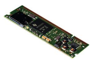
The IGEP COM AQUILA (IGEP0033) is an industrial processor module with 256 MB RAM plus 128 MB FLASH, it is based in ARM Cortex-A8 AM335x CPU up to 1GHz with SODIMM200 form factor size.
 |
 |
 |
Getting started
One of the most interesting parts about IGEP COM AQUILA Board is the versatility that offers to baseboard designers to implement their own specific solution. But this versatility represents too an obstacle to start developing the baseboard.
To resolve this initial obstacle, this guide does an abstract about every single part, each part is classified by:
- Power, system boot and resets
- Peripherals
Power, system boot and resets
This part can be helpful to power up and power down the full system correctly.
Power sources
Input Power sources
- VIN is the main source voltage that generates all the necessary internal voltages to IGEP COM AQUILA. VIN source needs 5V, read the design rules to determine the maximum current load applied.
- VBACKUP is RTC backup power supply used to keep alive the hardware clock.
Output Power sources
- VOUT is a linear regulator output source that offers 3V3 and 1A.
- VREFP_ADC is a supply voltage used for AM335x analog digital converters.
Power sources design rules
- IGEP COM AQUILA uses a TPS73701, this LDO converts 5V (VIN input) to 3V3 (VOUT output), so you can use the following formula to calculate the maximum VIN current consumption: Ivin (maximum supply current) = 550 mA (internal maximum supply current) + Ivout (Vout maximum output current used).
- More information at IGEP AQUILA EXPANSION Hardware Reference Manual section 6.1
System boot
BOOTMODE pin
- BOOTMODE is used to setup a boot priority sequence. BOOTMODE is equal to #SYS_BOOT4 and it has a 100K PU resistor.
BOOTMODE design rules
- It is recommendable add a jumper header (or switch) series with a 100R resistor tied to GND in your base board to manage boot priority sequence. For example: If you want to reflash the internal NAND memory from microSD card you will need to unmount the jumper.
- More information at IGEP AQUILA EXPANSION Hardware Reference Manual section 6.1 and IGEP AQUILA EXPANSION Hardware Reference Manual section 5.8.
Resets
PMIC Resets
- PMIC_PWR_BTN: Drive to low to turn off power supply (long press). Also, this pin can generate interrupts to AM335x (short press).
AM335x Resets
- #RESET_OUT this pin is used to reset IC from IGEP COM AQUILA like LAN8720, it is managed by AM335x.
- #POR (Power on Reset) is a cold Reset used during AM335x power-up and power-down sequences, this pin is managed by PMIC into IGEP COM AQUILA.
- #RESET_IN is a warm Reset (also named fast reset).
Resets design rules
- Resets lines are very useful to restart ICs (LDOs, Transceivers, Level shifters, etc.).
- The most priority reset is PMIC_PWR_BTN, so it is important to use at least this one.
- More information at IGEP AQUILA EXPANSION Hardware Reference Manual section 6.1 and IGEP AQUILA EXPANSION Hardware Reference Manual section 5.7.
AM335x peripherals
This part can be helpful to expand correctly the AM335x peripherals. AM335x peripherals are expanded through SODIMM200 connector and they are classified by:
- Dedicated lines: These lines were designed to work with a specific functionality. Change its functionality its not possible or recommended.
- Optional lines: These lines were designed to work with different functionalities. AM335x Mux peripheral is used to select one functionality. Mux options are vast, at the beginning can be difficult and tedious change some configurations. Before configure mux, use the following tips to avoid problems:
- Mux can connect multiple pads at the same peripheral, this improper use can damage the processor. Before configure mux, revise that this peripheral is not used in other pads in your design. Read each peripheral chapter to implement your initial design and use the resources available above to revise your implementation.
- Some peripherals are only available if you place or replace some resistances into IGEP COM AQUILA. See IGEP COM AQUILA Hardware Reference Manual section 6.1 to get more information.
- Some pads share internal components. See IGEP COM AQUILA Hardware Reference Manual section 6.1 to get more information.
- Some SODIMM pads share an AM335x pad. See IGEP COM AQUILA Hardware Reference Manual section 6.1 to get more information.
Finally, the second part of this manual we are going to modify software to change Mux configuration properly.
Ethernet
Dedicated Ethernet
IGEP COM AQUILA uses LAN8720 transceiver to add Ethernet communication. IGEP AQUILA EXPANSION Public Schematics adapts SODIMM lines for a RJ-45 connector.
| Name | SODIMM pad | AM335x pad |
| ETN_TXN | 19 | - |
| #ETN_LED2 | 20 | - |
| ETN_TXP | 21 | - |
| ETN_3V3 | 22 | - |
| ETN_RXN | 23 | - |
| #ETN_LED1 | 24 | - |
| ETN_RXP | 25 | - |
Ethernet design rules
- For Ethernet data lines: TX differential lines (ETN_TXN and ETN_TXP) and RX differential lines (ETN_RXN and ETN_RXP)
- Equal length and symmetric with regards of shape, length, and via count.
- Maintain 100R differential impedance in the layout traces.
- Isolate differential pairs from nearby signals and circuitry to maintain the signal integrity.
- Among PHY vendors, the 25mm rule is considered good design practice for EMI considerations. The intention is to isolate the PHY from the magnetics.
- Common mode capacitors in data lines are not necessary because IGEP COM AQUILA includes them.
- If the magnetic is a discrete component:
- The distance between the magnetic and the RJ-45 needs to have the highest consideration and be kept to under 25mm of separation.
- The distance between the SODIMM and the magnetics needs to be 20mm or greater.
USBs
Dedicated USB Host
IGEP COM AQUILA uses USB1 peripheral as USB 2.0 Host. IGEP AQUILA EXPANSION Public Schematics adapts SODIMM lines for an USB Type A receptacle.
| Name | SODIMM pad | AM335x pad |
| USBH_VBUSEN | 27 | F15 |
| #USBH_OC | 28 | R13 |
| USBH_DM | 29 | R18 |
| USBH_VBUS | 30 | T18 |
| USBH_DP | 31 | R17 |
Dedicated USB OTG
IGEP COM AQUILA uses USB0 peripheral as USB 2.0 OTG. IGEP AQUILA EXPANSION Public Schematics adapts SODIMM lines for an USB Type mini AB receptacle.
| Name | SODIMM pad | AM335x pad |
| USBOTG_ID | 33 | P16 |
| USBOTG_VBUSEN | 34 | F16 |
| USBOTG_DM | 35 | N18 |
| #USBOTG_OC | 36 | V17 |
| USBOTG_DP | 37 | N17 |
| USBOTG_VBUS | 38 | P15 |
USB design rules
- For USB data lines: USB1 (USBH_DM and USBH_DP) and USB0 (USBOTG_DM and USBOTG_DP)
- Maintain 90R +/- 15% differential impedance in the layout traces.
- Equal length and symmetric with regards of shape, length, and via count.
- Isolate differential pairs from nearby signals and circuitry to maintain the signal integrity.
- VBUS overcurrent protection: USB power source current must not be pass 500mA, you should apply a protection into the baseboard. IGEP AQUILA EXPANSION Public Schematics proposes a solution using TPS2051D IC.
- IGEP COM AQUILA includes into each USB peripheral a VBUS overvoltage protector.
I2C
Dedicated I2C
IGEP COM AQUILA uses I2C0 as a dedicated bus. I2C0 is shared with PMIC (0x2d address) and has 5K PU.
| Name | SODIMM pad | AM335x pad |
| I2C0_SCL | 41 | C16 |
| I2C0_SDA | 40 | C17 |
Optional I2C
IGEP COM AQUILA contains two optional I2C buses:
| Name | SODIMM pad | AM335x pad |
| I2C1_SCL | 44 | A16 |
| I2C1_SDA | 47 | B16 |
| I2C2_SCL | 46 | B17 |
| I2C2_SDA | 48 | A17 |
I2C design rules
- I2C0 should be your default option, but it could be interesting use Optional I2Cs if your external peripheral needs to use a huge transfer data connection.
- Optional I2Cs needs to be pulled up externally, 5K resistor tied to 3V3 must be necessary.
- IGEP COM AQUILA uses 3V3 voltage levels for I2C buses. In some cases, voltage translators like TXS0102 should be necessary to adapt voltage levels between ICs.
SPI
Optional SPI
IGEP COM AQUILA contains two optional SPI bus:
| Name | SODIMM pad | AM335x pad |
| SPI0_CS0 | 44 | A16 |
| SPI0_CS1 | 45 | C15 |
| SPI0_D0 | 46 | B17 |
| SPI0_D1 | 47 | B16 |
| SPI0_CLK | 48 | A17 |
| SPI1_CS0 | 60 | E15 |
| SPI1_CS1 | 59 | E16 |
| SPI1_D0 | 61 | E18 |
| SPI1_D1 | 62 | E17 |
| SPI1_CLK | 68 | H16 |
SPI design rules
- Optional SPI1 is not recommended to use, because some lines are shared with UART0 (Kernel Debug UART).
- IGEP COM AQUILA uses 3V3 voltage levels for SPI buses. In some cases, voltage translators like TXS0102 should be necessary to adapt voltage levels between ICs.
MMC
Dedicated MMC
IGEP COM AQUILA uses MMC0 from on board uSD card reader, but this pins are available into SODIMM connector too:
| Name | SODIMM pad | AM335x pad |
| MMC0_CD | 95 | A13 |
| MMC0_DAT0 | 96 | G16 |
| MMC0_DAT1 | 97 | G15 |
| MMC0_DAT2 | 98 | F18 |
| MMC0_DAT3 | 99 | F17 |
| MMC0_CMD | 100 | G18 |
| MMC0_CLK | 101 | G17 |
Optional MMC
IGEP COM AQUILA contains an optional MMC bus called MMC1:
| Name | SODIMM pad | AM335x pad |
| MMC1_CD | 51 | B13 |
| MMC1_DAT0 | 52 | K18 |
| MMC1_DAT1 | 53 | L18 |
| MMC1_DAT2 | 54 | L17 |
| MMC1_DAT3 | 55 | L16 |
| MMC1_CMD | 56 | V9 |
| MMC1_CLK | 57 | U9 |
MMC design rules
- MMC0 can not be used by SODIMM connector and on board uSD card reader at the same time.
- MMC1 is not bootable during system boot process using the bootmode pad.
- MMC1 bus is a good option to expand memory capacities or use as a backup memory.
- MMC bus needs PU resistors to avoid unknown signals. 10K PU resistors tied to 3V3 must be necessary in lines:SD1_Dx, SD1_CD and SD1_CLK.
- Optional: low resistance resistors could be necessary to equalize bus impedances. Use 10R series resistors in lines: SD1_Dx, SD1_CD and SD1_CLK .
UART
Optional UARTs
IGEP COM AQUILA contains six optional UARTs buses:
| Name | SODIMM pad | AM335x pad |
| UART0_TX | 59 | E16 |
| UART0_RX | 60 | E15 |
| UART0_CTS | 61 | E18 |
| UART0_RTS | 62 | E17 |
| UART1_TX | 63 | D15 |
| UART1_RX | 64 | D16 |
| UART1_CTS | 65 | D18 |
| UART1_RTS | 66 | D17 |
| UART2_TX | 52 | K18 |
| UART2_RX | 53 | L18 |
| UART3_TX | 45 | C15 |
| UART3_TX | 54 | L17 |
| UART3_RX | 55 | L16 |
| UART3_RX | 74 | C18 |
| UART4_TX | 76 | J18 |
| UART4_RX | 81 | K15 |
| UART5_TX | 67 | J17 |
| UART5_RX | 68 | H16 |
| UART5_CTS | 97 | G15 |
| UART5_RTS | 96 | G16 |
UART design rules
- IGEP COM AQUILA uses UART0 as a Kernel Debug Peripheral. This UART is an inexpensive method to detect and repair system issues. It is recommendable use another UART instead of UART0 to preserve this functionality.
- UART5_RTS and UART5_CTS are shared with MMC0 (uSD card reader), don't use both peripherals at the same time. Find more information at IGEP COM AQUILA Hardware Reference Manual section 6.1
- IGEP COM AQUILA uses 3V3 voltage levels for UART buses. In some cases, voltage translators like TXS0102 should be necessary to adapt voltage levels between ICs.
Video
Optional Video
IGEP COM AQUILA contains a LCD controller. This peripheral uses a Display Pixel Interface to transmit the information.
| Name | SODIMM pad | AM335x pad |
| LCD_D0 | 117 | U10 |
| LCD_D1 | 118 | U12 |
| LCD_D2 | 119 | V13 |
| LCD_D3 | 120 | U4 |
| LCD_D4 | 121 | V2 |
| LCD_D5 | 122 | V3 |
| LCD_D6 | 123 | V4 |
| LCD_D7 | 124 | T5 |
| LCD_D8 | 125 | T10 |
| LCD_D9 | 126 | T12 |
| LCD_D10 | 127 | T2 |
| LCD_D11 | 128 | T3 |
| LCD_D12 | 130 | T4 |
| LCD_D13 | 131 | U1 |
| LCD_D14 | 132 | U2 |
| LCD_D15 | 133 | U3 |
| LCD_D16 | 134 | T11 |
| LCD_D17 | 135 | R12 |
| LCD_D18 | 136 | U13 |
| LCD_D19 | 137 | R1 |
| LCD_D20 | 138 | R2 |
| LCD_D21 | 139 | R3 |
| LCD_D22 | 140 | R4 |
| LCD_D23 | 141 | T1 |
| LCD_HSYNC | 143 | R5 |
| LCD_VSYNC | 144 | U5 |
| LCD_OE_ACD | 145 | R6 |
| LCD_SCLK | 146 | V5 |
Video design rules
- IGEP AQUILA EXPANSION Public Schematics adapts SODIMM video lines to HDMI Transmitter.
- Optionally: common mode capacitors could be added between video data lines and GND for high frequency attenuation. Typical capacitance values should be between 22pF and 47pF.
- Optionally: low resistance resistors could be necessary to equalize bus impedances. 10R series resistors to data and clock lines could be necessary.
Audio
Optional Audio
IGEP COM AQUILA has a MCASP transceiver, it is a digital multichannel audio serial port used by microprocessors, DSPs and popular industry audio CODECs that implement the inter-IC sound bus standard (I2S) and Intel AC97 standard. IGEP AQUILA EXPANSION Public Schematics uses this bus to send audio data to HDMI transceiver.
| Name | SODIMM pad | AM335x pad |
| MCASP0_ACLKR | 86 | B12 |
| MCASP0_ACLKR | 67 | J17 |
| MCASP0_ACLKR | 75 | U18 |
| MCASP0_ACLKR | 146 | V2 |
| MCASP0_ACLKX | 42 and 95 | A13 |
| MCASP0_ACLKX | 52 | K18 |
| MCASP0_ACLKX | 131 | U1 |
| MCASP0_ACLKX | 158 | V16 |
| MCASP0_AHCLKR | 73 | C12 |
| MCASP0_AHCLKX | 85 | A14 |
| MCASP0_AHCLKX | 81 | K15 |
| MCASP0_AXR0 | 83 | D12 |
| MCASP0_AXR0 | 54 | L17 |
| MCASP0_AXR0 | 153 | T16 |
| MCASP0_AXR0 | 133 | U3 |
| MCASP0_AXR1 | 84 | D13 |
| MCASP0_AXR1 | 53 | L16 |
| MCASP0_AXR1 | 123 | V4 |
| MCASP0_AXR2 | 86 | B12 |
| MCASP0_AXR2 | 73 | C12 |
| MCASP0_AXR2 | 68 | H16 |
| MCASP0_AXR2 | 120 | U4 |
| MCASP0_AXR2 | 146 | V2 |
| MCASP0_AXR3 | 85 | A14 |
| MCASP0_AXR3 | 87 | C13 |
| MCASP0_AXR3 | 124 | T5 |
| MCASP0_AXR3 | 122 | V3 |
| MCASP0_FSR | 87 | C13 |
| MCASP0_FSR | 76 | J18 |
| MCASP0_FSR | 79 | V12 |
| MCASP0_FSR | 122 | V3 |
| MCASP0_FSX | 51 | B13 |
| MCASP0_FSX | 53 | L18 |
| MCASP0_FSX | 72 and 154 | U16 |
| MCASP0_FSX | 132 | U2 |
Audio design rules
- The MCASP consists of independent transmitter and receiver sections with independent clock generation and frames synchronization. For example: If you only need to transfer audio the MCASP0_*R lines are not necessary to be used.
- The MCASP1 cannot be used.
ADCs
Dedicated ADCs
AM335x includes a touchscreen controller and analog-to-digital converter subsystem. It is an 8-channel general-purpose analog-to-digital converter (ADC) with optional support for interleaving touchscreen (TS) conversions for a 4-wire, 5-wire, or 8-wire resistive panel. This controller can be configured for use in one of the following applications:
- 8 general-purpose ADC channels
- 4-wire TSC with 4 general-purpose ADC channels
- 5-wire TSC with 3 general-purpose ADC channels
- 8-wire TSC
| Name | SODIMM pad | AM335x pad |
| VADC | 184 | - |
| XN | 185 | B6 |
| XP | 186 | C7 |
| YN | 187 | B7 |
| YP | 188 | A7 |
| WIPER | 189 | C8 |
| ADC5 | 190 | B8 |
| ADC6 | 191 | A8 |
| ADC7 | 192 | C9 |
PWM
Optinal PWM
AM335x includes six PWM peripherals with 16 bits time-base with Period and Frequency control.
| Name | SODIMM pad | AM335x pad |
| EHRPWM0A | 42 and 92 | A13 |
| EHRPWM0B | 51 | B13 |
| EHRPWM1A | 133 | U3 |
| EHRPWM1B | 120 | U4 |
| EHRPWM2A | 117 | U10 |
| EHRPWM2B | 125 | T10 |
GPIOs
Optional GPIOs
All the optional SODIMM pins can be used as GPIOs. The following table shows some recommended SODIMM pins to be used as GPIOs:
| Name | SODIMM pad | AM335x pad |
| KP_COL0 | 72 | U16 |
| KP_COL1 | 73 | C12 |
| KP_COL2 | 74 | C18 |
| KP_COL3 | 75 | U18 |
| KP_ROW0 | 77 | A15 |
| KP_ROW1 | 78 | D14 |
| KP_ROW2 | 79 | V12 |
| KP_ROW3 | 80 | T13 |
| GPIO0 | 148 | V14 |
| GPIO1 | 149 | U14 |
| GPIO2 | 150 | T14 |
| GPIO3 | 151 | U15 |
| GPIO5 | 153 | T16 |
| GPIO6 | 154 | V15 |
| GPIO7 | 155 | R14 |
CAN
CAN is a vehicle bus standard designed to allow microcontrollers and devices to communicate with each other within a vehicle without a host computer.
Optional CAN
| Name | SODIMM pad | AM335x pad |
| DCAN0_TX | 76 | J18 |
| DCAN0_RX | 81 | K15 |
| DCAN0_TX | 65 | D18 |
| DCAN0_RX | 66 | D17 |
| DCAN1_TX | 64 | D16 |
| DCAN1_RX | 63 | D15 |
| DCAN1_TX | 101 | G17 |
| DCAN1_RX | 100 | G18 |
Start a new hardware design of own IGEP AQUILA EXPANSION
IGEP AQUILA EXPANSION is an Open Source board designed for fast prototyping of your own projects for IGEP COM AQUILA. You can use the following resources as a model for your design:
- IGEP AQUILA EXPANSION Mechanical Layout PCB for Altium designers.
- Mechanical dimension implementation.
- Footprints
- IGEP AQUILA EXPANSION Mechanical Layout PDF
- Mechanical dimension implementation.
You have successfully completed this chapter of the guide.
| |

|
If you have any question, don't ask to ask at the IGEP Community Forum or the IGEP Community Chat | 
|