


Pau pajuelo
TODO:
Update peripheral tutorials, finish gpio example program
Categorize new tutorials
Upgrade ethernet gadget tutorial for new IGEP firmware and VM
Finish tutorials below
Upgrade IGEP Technology Devices Guides
Link all development tools documentation when possible
Using IGEP WLAN to communicate
Overview
If your IGEP Processor Board has WIFI interface you can connect to it without any cable. You can open a SSH session in your computer and interact with your Board from your console. Here is how to.
Requirements
There are some requisites to follow this guide:
- IGEP Processor Board with WIFI
- Host computer with WIFI
- MicroSD Card (optional: If your board has Poky Firmware)
- PuTTy program
Update pre-installed software
NOTE: Follow these steps if you use an older firmware release
(from How to create a SD-card with the latest software image)

|
This How-To was tested IGEP SDK Virtual Machine, but most of the contents are valid also for other GNU/Linux distributions.
There is no guarantee that this will work on other ones. |
Create IGEP Firmware bootable SD-card
IGEP AM335x - The first thing you'll do is download the latest firwmare from ISEE site Yocto IGEP AM335x
IGEP OMAP 3 - Start session in IGEP SDK Virtual Machine. The first thing you'll do is download the latest firwmare from ISEE site Yocto IGEP OMAP 3
IGEP SMARC i.MX6 Dual/Quad - The first thing you'll do is download the latest firwmare from ISEE site Yocto IGEP SMARC i.MX6 Dual/Quad
IGEP SMARC i.MX6 DualLite - The first thing you'll do is download the latest firwmare from ISEE site Yocto IGEP SMARC i.MX6 DualLite
IGEP SMARC i.MX6 Solo - The first thing you'll do is download the latest firwmare from ISEE site Yocto IGEP SMARC i.MX6 Solo
- Select Products -> Processor Boards
- Click on your processor board product.
- Click on Software tab
- Click on IGEP Firmware
- Select Download icon.
Once the file is downloaded you can create bootable SD-Card, under Linux, untar the IGEP
tar jxf igep_firmware-yocto-*.tar.bz2
cd igep_firmware-yocto-*
Insert a SD-Card media and use the igep-media-create script to copy the firmware to SD-Card media.
./igep-media-create -–mmc <mmc> --image <image file> --machine <machine>
where:
<mmc> - is the SD-Card device of your computer.
<image file> - is the file that contains bootloader, kernel and rootfs image.
<machine> - is the IGEP Processor Board. Available options are:
- igep0020 - For IGEP v2 Processor Board
- igep0030 - For IGEP COM MODULE Processor Board
- igep0032 - For IGEP COM PROTON Processor Board
- igep0033 - For IGEP COM AQUILA Processor Board
- igep0046 - For IGEP iMX6 Processor Board
For example, assuming the SD-card device takes '/dev/sdf' and you have an IGEPv2 board ('igep0020'), type
./igep-media-create --mmc /dev/sdf --machine igep0020 --image demo-image-sato-igep00x0.tar.bz2
For example, assuming the SD-card device takes '/dev/sdb' and you have an IGEP COM MODULE ('igep0030'), type
./igep-media-create --mmc /dev/sdb --machine igep0030 --image demo-image-sato-igep00x0.tar.bz2
These methods should give you a bootable SD-card.
Booting IGEP device and login/connect methods
Insert the bootable SD-card media into the micro-SD card socket of IGEP device and power on it. This should result in a running system with Sato graphical desktop root filesystem built by Yocto.
If you want login in/connect to the system, you have several options:
- Serial debug link, you should just plug serial cable to your computer
- Ethernet, you should assign an IP in the range 192.168.5.[2-254] and connect to target using a SSH client and connecting to 192.168.5.1
- Wifi, connect to IGEP_xx network, a dynamic IP should be assigned in your host and you can sign into the target connecting to 192.168.6.1
- USB ethernet gadget, connect a IGEP device to USB port of your computer, dynamic IP should be assigned in your host and you can sign into the target connecting to 192.168.7.1 o (if available) Graphical interface on plugged DVI/TFT display and USB Keyboard in IGEP device
The root password is empty, so to log in type 'root' for the user name and hit 'Enter' at the Password prompt: (empty password) and you should be in.
Then, you could play and fun with IGEP board.
For example, you could flash the latest software image into internal FLASH memory ( How to flash the latest software image )

|
If you have any question, don't ask to ask at the IGEP Community Forum or the IGEP Community Chat | 
|
Connect to IGEP network
Follow these steps to connect to your IGEP device:
- Click on the Network Manager Tray icon.
- Select IGEP_<xx> network, where <xx> is different for every IGEP device, to connect.

|

|
Click to enlarge image
Connect to IGEP
Follow these steps to get a remote shell prompt:
- Open PuTTy program
- Host Name:192.168.1.1
- Port: 22
- Connection type: SSH
- Click Open, accept Security Alert and login as root user

|

|

|

|
Click to enlarge image
Note that a DHCP IP address in range 192.168.6.10-192.168.6.254 should be given to your host PC. The IGEP device should have IP address 192.168.6.1.
Troubleshooting
WARNING: REMOTE HOST IDENTIFICATION HAS CHANGED!
In the case of the SSH client in Linux, a changed host key results in the client refusing to connect and showing an remote host identification has changed error
@@@@@@@@@@@@@@@@@@@@@@@@@@@@@@@@@@@@@@@@@@@@@@@@@@@@@@@@@@@
@    WARNING: REMOTE HOST IDENTIFICATION HAS CHANGED!     @
@@@@@@@@@@@@@@@@@@@@@@@@@@@@@@@@@@@@@@@@@@@@@@@@@@@@@@@@@@@
IT IS POSSIBLE THAT SOMEONE IS DOING SOMETHING NASTY!
Someone could be eavesdropping on you right now (man-in-the-middle attack)!
It is also possible that the RSA host key has just been changed.
The fingerprint for the RSA key sent by the remote host is
8d:0b:29:f0:0a:a1:f5:56:0c:12:18:b0:26:02:6d:9d.
Please contact your system administrator.
Add correct host key in /home/eballetbo/.ssh/known_hosts to get rid of this message.
Offending key in /home/eballetbo/.ssh/known_hosts:57
RSA host key for 192.168.7.2 has changed and you have requested strict checking.
To fix the problem edit your ~/.ssh/known_hosts and remove the line corresponding to this host.
NFS in rootfilesystem
Don't use NFS in rootfilesystem combined with WIFI
igep.ini parameters
The kernel command line syntax is name=value1. These next parameters are supported in igep.ini since IGEP-X_Loader 2.4.0-2:
[kernel]
| Parameter Name | Description | Default value | Comments |
| kaddress | Kernel copy address | =0x80008000 | Hex memory address |
| rdaddress | Ram Disk location address | =0x81600000 | Hex memory address; disabled by default |
| serial.low | Serial number (low part) | =00000001 | Numeric |
| serial.high | Serial number (high part) | =00000000 | Numeric |
| revision | Revision ID | =0003 | Numeric |
| kImageName | Kernel, binary image name | =zImage | Kernel or binary image name |
| kRdImageName | Kernel RAM Disk Image Name | - | Ram Disk image name |
| MachineID | Machine ID (kernel ID) | ;IGEPv2 =2344 |
;Module =2717 ;Proton =3203 |
| Mode | Boot Mode | ;Linux kernel =kernel |
;Other image (like uboot) [binary image] |
[kparams]
| Parameter Name | Description | Default value | Comments |
| buddy | Enable/disable expansion board support | ;IGEPv2 Expansion Board support =igep0022 |
;Berlin and Paris Expansion Board support =base0010 New York Expansion =ilms0015 |
| console | Setup the kernel console parameters | =ttyO2,115200n8 | - |
| earlyprintk | Enable early printk | - | - |
| mem | Setup the Board Memory Configuration | =430M | - |
| boot_delay | Setup the boot delay | =0 | - |
| mpurate | Setup ARM Processor Speed | - | - |
| loglevel | Setup the loglevel | - | - |
| debug | Enable kernel debug output | - | - |
| fixrtc | Fix RTC variable | - | - |
| nocompcache | Configure nocompcache variable | =1 | - |
| omapfb.mode | Configure frame bugger configuration | =dvi:hd720-16@50 | ;Other configuration =dvi:1280x720MR-16@60 |
| vram | Configure Video RAM assigned to every frame buffer | - | - |
| omapfb.vram | Configure Video RAM assigned to every frame buffer | - | - |
| omapfb.debug | Configure frame buffer debug output | - | - |
| omapdss.debug | Configure DSS Video debug output | - | - |
| smsc911x.mac0 | Configure Board Ethernet Mac Address | =0xb2,0xb0,0x14,0xb5,0xcd,0xde | For IGEP BERLIN |
| smsc911x.mac1 | Configure Board Ethernet Mac Address | =0xb2,0xb0,0x14,0xb5,0xcd,0xdf | For IGEP BERLIN (only with IGEP PROTON) |
| smsc911x.mac | Configure Board Ethernet Mac Address | =0xb2,0xb0,0x14,0xb5,0xcd,0xde | For IGEPv2, IGEP PROTON, IGEP PARIS and IGEP BERLIN |
| ubi.mtd | Fot UBI FS boot | - | - |
| root | Configure root directory for MMC, NFS or UBI | ;For mmc memory =/dev/mmcblk0p2 rw rootwait |
;For flash memory =/dev/mtdblock2 |
| nfsroot | For NFS boot | - | - |
| rootfstype | For UBI FS boot | - | - |
| ip | For NFS boot | - | - |
| init | Assign init program | - | - |
| musb_hdrc.debug | USB debug | - | - |
| musb_hdrc.use_dma | USB over network | - | - |
| libertas.libertas_debug | Configure libertas debug | - | - |
| board.ei485 | Enable/disable RS485 | ;Enable RS485 =yes |
;Disable RS485 =no |
| board.modem | Enable/disable GPRS modem | ;Enable modem (IGEPv2 Expansion) =no |
;Enable modem (IGEPv2 Expansion) =yes |
| buddy.revision | Enable hardware buddy revision [A or B] | Only for base0010 =A |
Only for base0010 =B |
Connect using USB Ethernet Gadget/RNDIS driver
Overview
The Linux kernel has a class of drivers called USB Gadgets that allow you to use USB as a transport for a number of different protocols like serial, virtual file systems and Ethernet devices.
The USB OTG connector supports using the Ethernet Gadget to create a networking device over USB. From the client's (and host's) perspective this driver simply appears as another Ethernet device, enabling us to have Ethernet access on the board by hooking them up to a desktop, so this USB slave device can communicate with a properly configured USB host.
Requirements
There are some requisites to follow this guide:
- IGEP Processor Board
- MicroSD Card (optional: If your board has Poky Firmware)
- PuTTy program
Update pre-installed software
NOTE: Follow these steps if you use an older firmware release
(from How to create a SD-card with the latest software image)
|
|
This How-To was tested IGEP SDK Virtual Machine, but most of the contents are valid also for other GNU/Linux distributions.
There is no guarantee that this will work on other ones. |
Create IGEP Firmware bootable SD-card
IGEP AM335x - The first thing you'll do is download the latest firwmare from ISEE site Yocto IGEP AM335x
IGEP OMAP 3 - Start session in IGEP SDK Virtual Machine. The first thing you'll do is download the latest firwmare from ISEE site Yocto IGEP OMAP 3
IGEP SMARC i.MX6 Dual/Quad - The first thing you'll do is download the latest firwmare from ISEE site Yocto IGEP SMARC i.MX6 Dual/Quad
IGEP SMARC i.MX6 DualLite - The first thing you'll do is download the latest firwmare from ISEE site Yocto IGEP SMARC i.MX6 DualLite
IGEP SMARC i.MX6 Solo - The first thing you'll do is download the latest firwmare from ISEE site Yocto IGEP SMARC i.MX6 Solo
- Select Products -> Processor Boards
- Click on your processor board product.
- Click on Software tab
- Click on IGEP Firmware
- Select Download icon.
Once the file is downloaded you can create bootable SD-Card, under Linux, untar the IGEP
tar jxf igep_firmware-yocto-*.tar.bz2
cd igep_firmware-yocto-*
Insert a SD-Card media and use the igep-media-create script to copy the firmware to SD-Card media.
./igep-media-create -–mmc <mmc> --image <image file> --machine <machine>
where:
<mmc> - is the SD-Card device of your computer.
<image file> - is the file that contains bootloader, kernel and rootfs image.
<machine> - is the IGEP Processor Board. Available options are:
- igep0020 - For IGEP v2 Processor Board
- igep0030 - For IGEP COM MODULE Processor Board
- igep0032 - For IGEP COM PROTON Processor Board
- igep0033 - For IGEP COM AQUILA Processor Board
- igep0046 - For IGEP iMX6 Processor Board
For example, assuming the SD-card device takes '/dev/sdf' and you have an IGEPv2 board ('igep0020'), type
./igep-media-create --mmc /dev/sdf --machine igep0020 --image demo-image-sato-igep00x0.tar.bz2
For example, assuming the SD-card device takes '/dev/sdb' and you have an IGEP COM MODULE ('igep0030'), type
./igep-media-create --mmc /dev/sdb --machine igep0030 --image demo-image-sato-igep00x0.tar.bz2
These methods should give you a bootable SD-card.
Booting IGEP device and login/connect methods
Insert the bootable SD-card media into the micro-SD card socket of IGEP device and power on it. This should result in a running system with Sato graphical desktop root filesystem built by Yocto.
If you want login in/connect to the system, you have several options:
- Serial debug link, you should just plug serial cable to your computer
- Ethernet, you should assign an IP in the range 192.168.5.[2-254] and connect to target using a SSH client and connecting to 192.168.5.1
- Wifi, connect to IGEP_xx network, a dynamic IP should be assigned in your host and you can sign into the target connecting to 192.168.6.1
- USB ethernet gadget, connect a IGEP device to USB port of your computer, dynamic IP should be assigned in your host and you can sign into the target connecting to 192.168.7.1 o (if available) Graphical interface on plugged DVI/TFT display and USB Keyboard in IGEP device
The root password is empty, so to log in type 'root' for the user name and hit 'Enter' at the Password prompt: (empty password) and you should be in.
Then, you could play and fun with IGEP board.
For example, you could flash the latest software image into internal FLASH memory ( How to flash the latest software image )
|
|
If you have any question, don't ask to ask at the IGEP Community Forum or the IGEP Community Chat |
|
Connect to IGEP device
Linux
NOTE: You should have the usbnet module available for your Linux kernel. On most distributions, this is the case by default. If this is not the case for your distribution, you will need to enable USB networking support in the kernel. If you build your own kernel then you want 'CDC Ethernet support' in USB Network adaptors.
- In the file /etc/network/interfaces, you should add:
iface usb0 inet dhcp
- Plug an USB Type-A to USB Type-A mini cable between your host PC and the USB OTG from IGEP device. Use a powered USB Hub if you use IGEP COM MODULE or PROTON.
- If you use IGEP SDK VM you need to attach the removable device RNDIS driver.
- Type in a terminal:
sudo ifup usb0
- Revise that:
jdoe@ubuntu ~ $ ifconfig
...
usb0      Link encap:Ethernet  HWaddr 66:cc:f2:be:51:b6
          inet addr:192.168.7.10  Bcast:192.168.7.255  Mask:255.255.255.0
          inet6 addr: fe80::64cc:f2ff:febe:51b6/64 Scope:Link
          UP BROADCAST RUNNING MULTICAST  MTU:1500  Metric:1
          RX packets:14 errors:0 dropped:0 overruns:0 frame:0
          TX packets:44 errors:0 dropped:0 overruns:0 carrier:0
          collisions:0 txqueuelen:1000
          RX bytes:2496 (2.4 KB)  TX bytes:8794 (8.7 KB)
...
Troubleshooting
WARNING: REMOTE HOST IDENTIFICATION HAS CHANGED!
In the case of the SSH client in Linux, a changed host key results in the client refusing to connect and showing an remote host identification has changed error
@@@@@@@@@@@@@@@@@@@@@@@@@@@@@@@@@@@@@@@@@@@@@@@@@@@@@@@@@@@
@    WARNING: REMOTE HOST IDENTIFICATION HAS CHANGED!     @
@@@@@@@@@@@@@@@@@@@@@@@@@@@@@@@@@@@@@@@@@@@@@@@@@@@@@@@@@@@
IT IS POSSIBLE THAT SOMEONE IS DOING SOMETHING NASTY!
Someone could be eavesdropping on you right now (man-in-the-middle attack)!
It is also possible that the RSA host key has just been changed.
The fingerprint for the RSA key sent by the remote host is
8d:0b:29:f0:0a:a1:f5:56:0c:12:18:b0:26:02:6d:9d.
Please contact your system administrator.
Add correct host key in /home/eballetbo/.ssh/known_hosts to get rid of this message.
Offending key in /home/eballetbo/.ssh/known_hosts:57
RSA host key for 192.168.7.1 has changed and you have requested strict checking.
To fix the problem edit your ~/.ssh/known_hosts and remove the line corresponding to this host.
NFS in root filesystem
Don't use NFS in rootfilesystem combined with USB Ethernet Gadget
Windows and MAC OSX
Use IGEP SDK Virtual Machine to develop under IGEP Technology
How to use GPIOs
Overview
This How-To is meant to be a starting point for people to learn use GPIOs for IGEP v2 devices as quickly and easily as possible. For this how-to i used Linaro Headless with Kernel 2.6.35.y, Ubuntu 10.04 with Linaro Toolchain, IGEP v2 RC5 and GPIO driver.
There are more ways to use GPIOs in IGEP v2, but this one is very simple.
Feedback and Contributing
At any point, if you see a mistake you can contribute to this How-To.
Compile GPIO driver source code via Host
Download GPIO driver and Kernel 2.6.35.y source code. Extract files.
Edit GPIO driver Makefile's:
-In files: $/app/Makefile and $/lib/Makefile, make sure that your CROSS_COMPILE path is correct.
-In file: $/modules/Makefile, make sure that your CROSS_COMPILE path is correct and type your Kernel 2.6.35.y path.
We will use the ncurses program for set up Kernel configuration, if you don't have this program installed then you must install it with this command:
sudo apt-get install ncurses-dev
-Go to kernel path and type:
make ARCH=arm CROSS_COMPILE=arm-linux-gnueabi- igep00x0_defconfig
Exit Linux Kernel Configuration an return to Bash. Type:
make ARCH=arm CROSS_COMPILE=arm-linux-gnueabi- modules_prepare
File $/include/generated/autoconf.h was created
Finally compile GPIO driver, go to main Makefile path and compile all source code using make command.
Send binaries created from Host to Igep v2.
Install binaries via IGEP
Log with root user to install binaries.
Install module
Go to:$/modules and insert user-gpio-drv.ko into linux kernel with the following command:
insmod user-gpio-drv.ko
Check that user-gpio-drv.ko is currently loaded with the following command:
lsmod
The result will be similar at that:
root@localhost:~/gpio-driver/module# lsmod
Module                  Size  Used by
user_gpio_drv           1639  0
omap_wdt                3411  0
spidev                  4198  0
iommu                   8558  0
rtc_twl                 4411  0
rtc_core               11187  1 rtc_twl
twl4030_keypad          2970  0
The module is loaded until system halt.
Go to:$/lib. libgpio.so is here.
If a program is linked with shared libraries, Kernel seek in specific paths when program is executed. Now is necessary link the libgpio.so path to the environment variable LD_LIBRARY_PATH, use the following command:
export LD_LIBRARY_PATH=/root/gpio-driver/lib/
Check that libgpio.so is linked correctly. Go to:$/gpio-driver/app, gpio program is here. Type next command:
ldd gpio
ldd command, print shared library dependencies. The result will be similar at that:
root@localhost:~/gpio-driver/app# ldd gpio
	libgpio.so => /root/gpio-driver/lib/libgpio.so (0x40197000)
	libc.so.6 => /lib/libc.so.6 (0x401a0000)
	/lib/ld-linux.so.3 (0x4008a000)
The shared library is linked until system halt. Now you can execute gpio example program.
Testing driver
To make sure than driver works well, make the next test. I used GPIO_136(sdmmc2_dat4) and GPIO_137(sdmmc2_dat5) because IGEP v2 RC5(without WIFI) don't use them by default:
NOTE: For more information visit this page (under construction).
Configure Mux
Go to:/sys/kernel/debug/omap_mux, and change this mux configuration:
echo 0x104>sdmmc2_dat4
echo 0x104>sdmmc2_dat5
Use cat command to check it:
cat sdmmc2_dat4
cat sdmmc2_dat5
The result will be similar at that:
root@localhost:/sys/kernel/debug/omap_mux# cat sdmmc2_dat4
name: sdmmc2_dat4.gpio_136 (0x48002164/0x134 = 0x0104), b ae4, t NA
mode: OMAP_PIN_INPUT | OMAP_MUX_MODE4
signals: sdmmc2_dat4 | sdmmc2_dir_dat0 | NA | sdmmc3_dat0 | gpio_136 | NA | NA | safe_mode
and
root@localhost:/sys/kernel/debug/omap_mux# cat sdmmc2_dat5
name: sdmmc2_dat5.gpio_137 (0x48002166/0x136 = 0x0104), b ah3, t NA
mode: OMAP_PIN_INPUT | OMAP_MUX_MODE4
signals: sdmmc2_dat5 | sdmmc2_dir_dat1 | cam_global_reset | sdmmc3_dat1 | gpio_137 | hsusb3_tll_stp | mm3_rxdp | safe_mode
Note: OMAP_PIN_INPUT=Input/Output pin and OMAP_PIN_OUTPUT=Output pin, for Read/Write test you need the first one. GPIO is configured in mode 4.
Read/Write test
Link GPIO_136 and GPIO_137 with a wire, these pins are located in J990 connector with numbers 7 and 9. I use the next connector to join them:
 |
 |
Now type next code:
root@localhost:~/gpio-driver/app# ./gpio input 136
root@localhost:~/gpio-driver/app# ./gpio output 137 0
root@localhost:~/gpio-driver/app# ./gpio get 136
0
root@localhost:~/gpio-driver/app# ./gpio output 137 1
root@localhost:~/gpio-driver/app# ./gpio get 136
1
root@localhost:~/gpio-driver/app#
The results (CMOS Voltages: 0V-1V8):
 |
 |
The code above shows that driver works properly, GPIO_136 is configured like input and GPIO_137 is configured like output with value 0, when read GPIO_136 the result is 0. To make sure that works well, configure GPIO_137 with value 1, now GPIO_136 reads 1.
This driver have more options like IRQ, but is not explained here.
Other examples:What can I do with IGEP0020#How_to_handle_the_gpio-LED.27s
How to use UARTs
Overview
This How-To is meant to be a starting point for people to learn use UART for IGEPv2 devices as quickly and easily as possible. In this how-to, we use Linaro Headless with Kernel 2.6.35.y and UART test program
More information about UART.
Note: This program has a debug option using GPIOs to debug via oscilloscope, this option is useful to learnt about the Kernel latencies. Debug has set to "write" and "select" functions.
Feedback and Contributing
At any point, if you see a mistake you can contribute to this How-To.
Preparing IGEP
Configure UART1 and UART3 in IGEP with RS232 levels on J960 connector
To test UARTs we use UART1 (dev/ttyS0) and UART3 (dev/ttyS2) via J960 connector using RS232 standard.
NOTE: Make sure that you installed open SSH server. If you don't have it go here.
By default, UART1 is used by RS485 driver, we need to disable it, edit igep.ini file:
board.ei485= yes
UART1 is configured in RS232 driver, when igep line is replaced by (or type in -Maybe you don't found this line-):
board.ei485= no
By default, UART3 is used by Kernel serial console, we need to disable it, go to igep.ini file, comment next line:
console=ttyS2,115200n8
Check UARTs devices
Make sure that Kernel detects UARTs, type:
dmesg | grep tty
The result will be similar at that:
root@localhost:~/PROGRAM# dmesg | grep tty
[    0.000000] console [tty0] enabled
[    0.598999] serial8250.0: ttyS0 at MMIO 0x4806a000 (irq = 72) is a ST16654
[    0.784057] serial8250.1: ttyS1 at MMIO 0x4806c000 (irq = 73) is a ST16654
[    0.969085] serial8250.2: ttyS2 at MMIO 0x49020000 (irq = 74) is a ST16654
[    1.153503] serial8250.3: ttyS3 at MMIO 0x49042000 (irq = 80) is a ST16654
root@localhost:~/PROGRAM#
Get information about UARTs, type:
setserial -g /dev/ttyS[0123]
The result will be similar at that:
root@localhost:~/PROGRAM# setserial -g /dev/ttyS*
/dev/ttyS0, UART: 16654, Port: 0x0000, IRQ: 72
/dev/ttyS1, UART: 16654, Port: 0x0000, IRQ: 73
/dev/ttyS2, UART: 16654, Port: 0x0000, IRQ: 74
/dev/ttyS3, UART: 16654, Port: 0x0000, IRQ: 80
root@localhost:~/PROGRAM#
If you don't have setserial installed type:
apt-get install setserial
NOTE: Starting from Kernel 2.6.37.y, ttySx are named ttyOx. You need to edit source program.
Connect peripherals
Connect IGEPv2 board using J960 connector like this:
 J960
                  ------
    (Not used) x---| 1  2 |---o (Connect to 8)
(Connect to 9) o---| 3  4 |---x (Not used)
         (GND)·|---| 5  6 |---|· (GND)
     (Not used)x---| 7  8 |---o (Connect to 2)
(Connect to 3) o---| 9 10 |---x (Not used)
                  ------
Send some data
Use minicom to prove it, open two terminals via SSH and log with root user:
Terminal 1:
minicom -D /dev/ttyS0
Terminal 2:
minicom -D /dev/ttyS2
Type something in one terminal.

|
Schematics
RS232 Schematic Igep V2

|
Uart Schematic Igep Module

|
Compile and run program
Download program source.
As explained above, the program uses GPIO for debug option via oscilloscope, it is necessary install user-gpio-drv.ko driver inside Linux Kernel, more information here .
There are some interesting things to configure, before compiling the program. Open it, seek next lines:
//Define Array char size
#define SIZE 30
//Define Debug mode:0==Disable
#define DEBUG 0

//Define wait select
#define WAIT 5

//Set GPIO Debugger port
//Be sure that mux is correctly configured and GPIOs are not used
#define GPIO1 136
#define GPIO2 137
Constant SIZE: it determines the max number of char than can be sent
Constant DEBUG: it can break program infinite loop part, it can be useful to debug some errors, 0 (infinite loop) or positive number determine loop max entrances
Constant WAIT: it configurea select max time.
Constants GPIO1 and GPIO2: they configure GPIOs used for debug via oscilloscope. Take care to configure mux and don't use them for other purposes
Once you have installed module. Compile program using your Cross Compiler, I used arm-linux-gnueabi-:
arm-linux-gnueabi-gcc uart-test-beta1.c -o uart-test-beta1
Testing UART
Some tests do it:
Decode Characters
Decoded with ASCII table.

|

|

|
| Decoding "1\n" | Decoding "0\n" | Decoding "100000\n" |
Click to enlarge image
select timeout
Program sends information via UART1 but don't receive response via UART3, because only a process is executed. This problem is repeated every 5 seconds (constant WAIT=5) until other process sends information via UART3 at the same speed. If "select" hasn't been implemented, process would have stayed blocked.

|
| UART1=Blue and UART3=Green |
Click to enlarge image
RS232 Voltage params
More information here.

|
| Vpp=11.8V aprox , Vmin=-5.6V aprox |
Click to enlarge image
Speed Overview
Note that wave is degraded when speed is higher

|

|

|

|
| Overview signal to 300 bauds | Overview signal to 4800 bauds | Overview signal to 115200 bauds | Overview signal to 3000000 bauds |

|

|

|

|
| Specific wave to 300 bauds | Specific wave to 4800 bauds | Specific wave to 115200 bauds |
Specific wave to 3000000 bauds |
Click to enlarge image
Lag
You can see that RS232 have some lag between transmisions. This caused mainly by kernel process management. UART peripheral is controlled by Linux and It isn't a real-time operating system.

|
 select: blocked until all data is available. select: blocked until all data is available.
|
| Lag between UART1 and UART3 (300 bauds) | Lag between UART3 and UART1 (300 bauds) |
Click to enlarge image
This program have three I/O functions that connect to UART driver via ioctl: (read(), write() and select()). But select() and write() change process stat to sleep mode until system don't receive or transmit all information via UART. "select" function is used to prevent that read function can be blocked when data aren't available.
The next images (program with debug_gpio enabled and 300 bauds speed) show when process is executed or is waiting. Blue=UART1, Violet="write" and Green="select". When GPIO has HIGH value, process is blocked.

|

|

|

|
| select function time | Time between select and write | write function time | Time between write and select |
Click to enlarge image
In this case:
select: blocked until all data is available (LF char received).
write: blocked until all data is send to UART buffer.
Error test
Every full process the number is increased twice. Program checks that this condicion is true, if it isn't accomplished, process will be finish.

|
| Runs 16h without any transfer error (3000000 bauds) |
Getting started with IGEPv2 Expansion
|
|
Overview
This is the 1/3 chapter of IGEPv2 Expansion Tutorial Guide.
In this first chapter, we will learn how to connect some expansion peripherals.
Requirements
In these tutorials we are going to need the following components :
- IGEPv2, +5V DC power supply, Ethernet cable and a PC with Linux or Windows.
- Powertrip 4.3" or Seiko 7" screen if you need a touch screen.
- DB9 connector and USB serial converter to follow serial communication tutorial
- 4 pin connector for CAN Bus with another IGEPv2 and Expansion to follow CAN Bus communication tutorial
- SIM card with an antenna to follow Telit modem tutorial
- Composite video cable, composite video output peripheral (PAL or NTSC) and a screen to follow TVP5151 tutorial
Getting started
Connect IGEPv2 Expansion with IGEPv2 Board
Basic
The IGEPv2 Expansion connects to the IGEPv2 Board through J990, JA41, JA42, JC30 and J960 connectors. Some IGEPv2 Expansion may include three jumpers, you should remove it because they are designed for test and lab purposes. Just take a look on the figure below to mount it:
 |
 |
TFT and Touchscreen
Basic

Know more
IGEPv2 Expansion integrates LCD backlight driver (TPS61081) and touch screen controller (TSC2046), a 4-wire touch screen controller which supports a low voltage I/O interface from 1.5V to 5.25V.
Serial port
Basic
IGEPv2 Expansion integrates a DB9 RS232 connector. Plug a DB9 cable.
Know more
This peripheral (UART 3) can be used to debug system using kernel traces, getting a remote prompt, etc.
VGA monitor
Basic

|

|
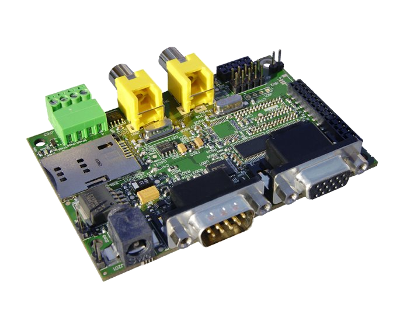
IGEPv2 Expansion integrates a VGA connector, the output VGA signal is equal to HDMI connector. Plug a monitor with VGA input.
Know more
This output is controled by ADV7125KSTZ140 Integrated Circuit.
CAN bus
Basic

Know more
This output is controled by MICROCHIP MCP2515. J703 is a 3.5 mm pitch terminal blocks 4 Positions:
| Signal Name | Pin # |
Description |
| VDD_CAN | J703:1 | Supply Voltage (+5V DC) |
| CANL | J703:2 | CAN Low-Level Voltage I/O |
| GND | J703:3 | Ground |
| CANH | J703:4 | CAN High-Level Voltage I/O |
GSM/GPRS modem
Basic

|
 |
| GSM-GPRS antenna (highly recommended) | SIM card reader |
IGEPv2 Expansion integrates a GSM/GPRS modem to make phone calls or to send SMS or to write and read data from it, etc.
Know more Modem chip Telit GE865 is a small GSM/GPRS Ball-Grid-Array BGA module with next main features:
- Quad-band EGSM 850 / 900 / 1800 / 1900 MHz
- Power consumption (typical values)
- Power off: ‹ 62 uA
- Idle (registered, power saving): 1.6 mA @ DRX=9
Composite Video Decoder
Basic

Know more
Analog input is decoded by TVP5151.
----
You have successfully completed this chapter of the guide.
|
|
|
If you have any question, don't ask to ask at the IGEP Community Forum or the IGEP Community Chat |
|
|
|
What can i do with igepv2 expansion
|
|
Overview
This is the 2/3 chapter of IGEPv2 Expansion Tutorial Guide.
We will learn some basic tasks such add support to IGEPv2 Expansion, control some peripherals, etc.
What can I do
How to use Serial communication (DB9 connector)
Basic
RS232 link for UART 3 (/dev/ttyO2) can be obtained through J502 DB9 connector. You can use PuTTy to get a shell prompt to IGEP:
- Power up IGEPv2
- Open PuTTy.
- Choose Serial line. If you are running PuTTy on Windows, the Serial line will be like (COM1 or COM2 or COM3, etc.). If you are running PuTTy on Ubuntu, the Serial line will be like (/dev/ttyS0 or /dev/ttyS1 or /dev/ttyS3, etc.). Note that if you are using a USB->Serial converter, the Serial line will be like /dev/ttyUSB0
- Configure Speed to 115200
- Select Serial Connection type
- Press on Open button
- You will successfully started the console.

|

|
Know more
Read this tutorial to learn about UARTs.
How to use TFT and Touchscreen
Seiko a Powertip touch screens are not supported by default in IGEPv2. Use the following steps for it:
- Log into IGEPv2 (via SSH, as shown in the previous chapter), and run the following commands:
ssh root@192.168.5.1
mkdir /tmp/temp
mount -t jffs2 /dev/mtdblock1 /tmp/temp
vi /tmp/temp/igep.ini
- In Seiko screen add the following line:
omapdss.def_disp=lcd-70
- In Powertip screen add the following line:
omapdss.def_disp=lcd-43
- Save changes and reboot your IGEP Device to finish it.
How to use Telit Modem
Basic
Telit modem is not supported by default in IGEPv2. Use the following steps for it:
- Log into IGEPv2 (via SSH, as shown in the previous chapter), and run the following commands:
ssh root@192.168.5.1
mkdir /tmp/temp
mount -t jffs2 /dev/mtdblock1 /tmp/temp
vi /tmp/temp/igep.ini
- Add the following line (press i to insert content):
buddy.modem=yes
- Save changes (ESC -> :wq -> Enter) and reboot your IGEP Device
- Power up the modem. You can power off using again these commands:
echo 0 > /sys/class/gpio/gpio140/value
echo 1 > /sys/class/gpio/gpio141/value
sleep 1
echo 0 > /sys/class/gpio/gpio141/value
- Once the modem is on (led D401, near SIM card reader, is blinking now), you can interact with it via UART 2. You can use Microcom to comunicate with it from the serial debug console:
microcom -s 115200 /dev/ttyO1
- To check the modem status use the command:
at
- Answer should be OK.
- Now unlock it by inserting your SIM card PIN number. Use the command:
at+cpin=<PIN>
- If you correctly inserted the PIN number, the answer should be OK. If you fail more than 3 times, your SIM card will lock and you will have to insert PUK number.
- Now you are ready to use the GSM/GPS modem.
Examples
If you successfully followed the the previous instructions, you are ready to test the GSM/GPRS modem. Here are some examples:
You can check the complete list of AT commands at the Official manufacturer Software User Guide.
Test received signal strength
Use the instruction:
at+csq
The answer should be: +CSQ: X,0, where X is the signal strenght. For example 12 is poor and 18 is good. If the answer is +CSQ:99,99 you should check your coverage or use an antenna
Making a phone call
Use the instruction, replace number_to_call with your number:
atd number_to_call
Press any key to end call
NOTE: If "NO CARRIER" message appears, check your coverage or use an antenna.
Sending a SMS
First of all, you need to configure the SMS format type. Telit GE865 GSM/GPRS supports PDU format and Text format. We use Text format. Type the following command:
AT+CMGF=1
There are so many ways in this modem to send a message. Here you have a simple example. Use the instruction, replace destination_number with your number:
at+cmgs= destination_number
> insert here your text message
When you are ready to send your message use Ctrl+Z to send it.
If you want to cancel or restart the message press ESC.
NOTE: If "NO CARRIER" message appears, check your coverage or use an antenna.
NOTE: Don't use special characters in SMS text message like <`´'">.
Know more
Here you have the official manuals from the manufacturer's webpage:
How to use TVP5151 Video Decoder
Basic
Use the following steps to capture analog video:
- Connect a video composite input to J501 connector from IGEPv2 Expansion (near CAN Bus)
- Connect a screen, for example HDMI monitor.
- Log into IGEPv2 (via SSH, as shown in the previous chapter), and run the following commands:
ssh root@192.168.5.1
- Now you have a remote igep terminal
- Refresh repositories and accept it.
zypper ref
- Install video4linux2 plugin
zypper in gst-plugins-good-video4linux2
- Load OMAP ISP kernel module
modprobe omap3-isp
- Configure ISP, for PAL resulution use 720x576 for NTSC resolution use 720x480:
media-ctl -r -l '"tvp5150 2-005c":0->"OMAP3 ISP CCDC":0[1], "OMAP3 ISP CCDC":1->"OMAP3 ISP CCDC output":0[1]'
media-ctl -v --set-format '"tvp5150 2-005c":0 [UYVY 720x480]'
media-ctl -v --set-format '"OMAP3 ISP CCDC":0 [UYVY 720x480]'
media-ctl -v --set-format '"OMAP3 ISP CCDC":1 [UYVY 720x480]'
- Export display
export DISPLAY=:0.0
- Launch gstreamer
gst-launch-0.10 -v v4l2src device=/dev/video2 queue-size=8 ! video/x-raw-yuv,format=\(fourcc\)UYVY,width=720,height=480 ! ffmpegcolorspace ! autovideosink
- Now you can see in your IGEP screen a result similar like this

|
Know more
You can use other programs like yavta
How to use EEPROM
Basic
The IGEP0022 expansion board provides an AT24C01B serial EEPROM memory which is connected to the OMAP via I2C (register 50).
Use i2c-tools to manage it:
i2cget <bus> <chip> <register>
i2cset <bus> <chip> <register> <value>
For example, the following writes the value 0x22 to register 0x10 of device 0x50 on i2c bus 2:
i2cset -f -y 2 0x50 0x10 0x22
i2cget -f -y 2 0x50 0x10
Know more
See also: i2dump(8), i2cget(8) and i2cset(8) man page
How to use CAN bus (under construction)
You have to connect the two boards like this:
IGEPv2 1             IGEPv2 2
.---                 .---
| 1 |-X            X-| 1 |
| 2 |------------------| 2 |
| 3 |------------------| 3 |
| 4 |------------------| 4 |
.---                 .---
If this is your first time accessing CAN bus, check J702 jumper is not connected before follow this tutorial. If you don't have this jumper, don't worry because its function is only for testing.
Now you can set up the interface (on all boards when using multiple IGEPv2 EXPANSION connected to a CAN network simultaneously):
/bin/ip link set can0 up type can bitrate 125000
If you want to receive CAN data, use:
candump can0
If you want to send CAN data, use:
cansend can0 -i 0x123 0xaa 0xbb 0xcc 0xdd
On the receiver side, you must see the following messages:
can0 123 [4] aa bb cc dd
Switch roles and try it again
----
You have successfully completed this chapter of the guide.
|
|
|
If you have any question, don't ask to ask at the IGEP Community Forum or the IGEP Community Chat |
|