


Difference between revisions of "User:Pau pajuelo"
From IGEP - ISEE Wiki
m |
m |
||
| Line 192: | Line 192: | ||
==== Copy Kernel to SD card ==== | ==== Copy Kernel to SD card ==== | ||
| − | + | *Kernel binary resides inside the directory:$(Kernel path)/arch/arm/boot/zImage. Copy binary to SD boot partition: | |
<pre>mv arch/arm/boot/zImage /media/boot/zImage</pre> | <pre>mv arch/arm/boot/zImage /media/boot/zImage</pre> | ||
| + | *Copy Kernel modules: | ||
| + | <pre>4 </pre> | ||
==== Enable ilms0015 support ==== | ==== Enable ilms0015 support ==== | ||
Revision as of 11:45, 14 August 2012
TODO:
Update peripheral tutorials
Categorize new tutorials
Upgrade ethernet gadget tutorial for new IGEP firmware and VM
Finish tutorials below
NOTES: Qt, Codeblocks and Eclipse are linked to main page:
Eclipse -> How to develop under Eclipse (copy manual) (refers at beginning VM and option to install Eclipse(under construction))
Qt -> How to develop under Qt (refers at begginin VM and option to install Qt (under construction))
Codeblocks (do it)
Upgrade ethernet gadget how to
Adapt IGEPv2 to IGEPv2 Expansion
How to use SPI (prove with new firmware, under construction)
Overview
This How-To is meant to be a starting point for people to learn use SPI for IGEP devices as quickly and easily as possible. In this how-to, we run an example program that reads and writes registers from 3-axis accelerometer (LIS3DH) included on the board IGEP New York.
Requirements
There are some requisites to follow this guide:
- IGEP SDK VM: follow the IGEP SDK SOFTWARE USER MANUAL (chapter 2.3 "Setting up and running the VM")
- IGEP Firmware: follow the IGEP SDK SOFTWARE USER MANUAL (chapter 6.1 "Create IGEP firmware bootable micro-sd card")
- IGEP COM MODULE and IGEP NEW YORK
- SPI example program (link program)
- MicroSD Card (at least 2Gbytes)
How Works
LIS3DH accelerometer: It is the accelerometer mounted in IGEP New York.
Omap3 SPI Peripheral: It is the hardware used to communicated with accelerometer and other SPI devices.
Omap2_mcspi: It is a bus driver than controls Omap3 SPI Peripheral.
Spi: It is a protocol driver that defines functions and strucs used in SPI bus.
Spidev: It is a device driver that export spi driver functionalities to userspace.
Lis3lv02d_spi: SPI glue layer for lis3lv02d
Lis31v02d: Device driver for LIS3DH accelerometer.
Exp_ilms0015: It is a startup program for IGEP New York. It attach lis31v02d with Spi driver.

|
More information about Linux Kernel SPI at:
Prepare Micro SD Card
Generate Micro SD Card (correct)
Open a terminal and use the following steps to download and generate a Micro SD card.
wget http://downloads.isee.biz/denzil/binary/igep_firmware-yocto-1.2.1-1.tar.bz2
tar jxf igep_firmware-yocto-*.tar.bz2
cd igep_firmware-yocto-*
Insert a SD-Card media and use the igep-media-create script to copy the firmware.
./igep-media-create -–mmc <mmc> --image demo-image-sato-igep00x0.tar.bz2 --machine igep0030
where <mmc> - is the SD-Card device of your computer. For example, assuming the SD-card device takes '/dev/sdb' type:
./igep-media-create --mmc /dev/sdb --machine igep0030 --image demo-image-sato-igep00x0.tar.bz2
This should give you a bootable SD-card with IGEP COM MODULE support.
Custom Micro SD Card
Get Linux kernel sources
We will get from git repository the kernel sources:
- Clone the Kernel git repository
git clone git://git.igep.es/pub/scm/linux-omap-2.6.git
$/home/jdoe> cd linux-omap-2.6
- Checkout your desired branch (we used for this howto 2.6.37.y)
git checkout origin/linux-2.6.37.y -b linux-2-6-37.y
Modify Linux Kernel Sources to attach Spidev to SPI driver
To read accelerometer registers from spidev, we need to attach spidev driver to spi driver at start up. So it is necessary to modify spi_board.
Go to $(Kernel path)/arch/arm/mach-omap2/exp-ilms0015.c and edit the next fields in bold words.
|
static struct spi_board_info lis3lv02d_spi_board_info __initdata = { .modalias = "spidev", //.modalias = "lis3lv02d_spi", .bus_num = -EINVAL, .chip_select = -EINVAL, .max_speed_hz = 1*1000*1000, .irq = -EINVAL, .mode = SPI_MODE_0, //.platform_data = &lis3lv02d_pdata, }; inline void __init ilms0015_lis3lv02d_init(int bus_num, int cs, int irq) { struct spi_board_info *spi = &lis3lv02d_spi_board_info; if ((gpio_request(irq, "LIS3LV02D IRQ") == 0) && (gpio_direction_input(irq) == 0)) gpio_export(irq, 0); else { pr_err("IGEP: Could not obtain gpio LIS3LV02D IRQ\n"); return; } spi->bus_num = bus_num; spi->chip_select = cs; spi->irq = OMAP_GPIO_IRQ(irq), spi_register_board_info(&lis3lv02d_spi_board_info, 1); } ... void __init ilms0015_init(void) { mux_partition = omap_mux_get("core"); /* Mux initialitzation for ilms0015 */ omap_mux_write_array(mux_partition, ilms0015_mux); /* 3-axis accelerometer */ ilms0015_lis3lv02d_init(1, 2, 174); /* Export some GPIO */ ilms0015_gpio_init(); } |
Now spi_register_board_info has all information necessary to attach spidev driver instead lis3lv02d_spi.
Compile Kernel
Export IGEP SDK sources:
source /opt/poky/1.2/environment-setup-armv7a-vfp-neon-poky-linux-gnueabi
- Configure the kernel
cd linux-omap-2.6
make ARCH=arm CROSS_COMPILE=arm-poky-linux-gnueabi- igep00x0_defconfig
- Build the kernel and Modules
make ARCH=arm CROSS_COMPILE=arm-poky-linux-gnueabi- zImage modules
Copy Kernel to SD card
- Kernel binary resides inside the directory:$(Kernel path)/arch/arm/boot/zImage. Copy binary to SD boot partition:
mv arch/arm/boot/zImage /media/boot/zImage
- Copy Kernel modules:
4
Enable ilms0015 support
By default, igep-media-create configured as igep0030, gives support only for IGEP Expansions Paris and Berlin. We need to configure igep.ini (located at bot partition) and gives support to IGEP New York:
| ; Machine configuration
;buddy=base0010 buddy.revision=B buddy=ilms0015 |
NOTE: “ilms0015” is the technical name of IGEP New York.
Test changes
Once you copy your new Kernel binaries and edit igep.ini:
- Power up your board with your new SD card
- Enable removable device: RNDIS/Ethernet Gadget
- Set up usb0 network device:
jdoe@ubuntu ~ $ sudo ifup usb0
jdoe@ubuntu ~ $ ifconfig usb0
usb0      Link encap:Ethernet  HWaddr 32:3a:b0:bc:cc:15
          inet addr:192.168.7.10  Bcast:192.168.7.255  Mask:255.255.255.0
          inet6 addr: fe80::303a:b0ff:febc:cc15/64 Scope:Link
          UP BROADCAST RUNNING MULTICAST  MTU:1500  Metric:1
          RX packets:53 errors:0 dropped:0 overruns:0 frame:0
          TX packets:46 errors:0 dropped:0 overruns:0 carrier:0
          collisions:0 txqueuelen:1000
          RX bytes:10584 (10.5 KB)  TX bytes:9203 (9.2 KB)

jdoe@ubuntu ~ $
Log in:
jdoe@ubuntu ~ $ ssh root@192.168.7.1
root@igep00x0:~#
Check your changes (spidev will be enabled):
root@igep00x0:/dev# lsmod

Module                  Size    Used by

rfcomm                48522   0

hidp                    13311   0

l2cap                   49001   4 rfcomm,hidp

bluetooth             67643   3 rfcomm,hidp,l2cap

libertas_sdio         13887   0

libertas                99318   1 libertas_sdio

option                 13044   0

usb_wwan              7196   1 option

usbserial              23870   2 option,usb_wwan

'''spidev                  4898   0 '''

root@igep00x0:/dev# ls /dev/spidev1.2

/dev/spidev1.2
“spidev1.2”: refers at McSPI1 bus 2. Now we can communicate to accelerometer using spi driver functions.
SPI Test program
Overview
This program is based in spidev_test and it was edited to run with LIS3DH accelerometer, program can be explained in four parts:
Connection properties: program lets change via parameters SPI configurations like: device, max speed, delay, bits per word, clock phase, clock polarity, etc. If you don't use any of this parameters program will use default options for LIS3DH communication.
Read mode: Reads a word from a register.
Write mode: Writes a word in a register.
Test mode: Reads X, Y and Z axes from accelerometer.
We recommend to read peripheral datasheet before use or modify program.
Compile program
The program source was compiled with Poky SDK but you can use other compilers like Linaro Toolchain:
arm-poky-linux-gnueabi-gcc spiexamplebeta2.c -o spiexampleb2
Copy your final binary to rootfs.
Test program
Read WHO_AM_I register(0Fh)
LIS3DH has this dummy register (See 8.6 chapter) as a device identification. Its value is 0x33:
root@igep00x0:~# ./spiexampleb2 -R 0F
spi mode: 0
bits per word: 8
max speed: 1000000 Hz (1000 KHz)
Value from 0F is: 33
root@igep00x0:~#
Read and Write CTRL_REG1 (20h)
This register is used to enable/disable: accelerometer and XYZ axes (See 8.8 chapter). The default value at startup is:
root@igep00x0:~# ./spiexampleb2 -R 20
spi mode: 0
bits per word: 8
max speed: 1000000 Hz (1000 KHz)
Value from 20 is: 07
root@igep00x0:~#
It means that accelerometer was disabled and X, Y and Z axes was enabled. For example we can disable X axe typing:
root@igep00x0:~# ./spiexampleb2 -W 20 -V 06
spi mode: 0
bits per word: 8
max speed: 1000000 Hz (1000 KHz)
Register to write 20 with value 06
root@igep00x0:~# ./spiexampleb2 -R 20
spi mode: 0
bits per word: 8
max speed: 1000000 Hz (1000 KHz)
Value from 20 is: 06
root@igep00x0:~#
Read accelerometer axes
| Finally we are going to read gravity force: LIS3DH has ±2g/±4g/±8g/±16g dynamically selectable full scale (See chapter 8.11). The axes values are expressed in two’s complement in 16 bits (See chapters 8.16, 8.17 and 8.18). | 
|
root@igep00x0:~# ./spiexampleb2 -T
spi mode: 0
bits per word: 8
max speed: 1000000 Hz (1000 KHz)
Accelerometer TEST
Values from X -64, Values from Y -15872 and Values from Z -256
root@igep00x0:~#
The next table shows results at different positions:
| Position | ±2g scale | ±4g scale | ±8g scale | ±16g scale |
 |
X = 832
Y = 1024 Z = 15680 |
X = 256 Y = 128 Z = 7872 |
X = 128 Y = 128 Z = 4032 |
X = 64 Y = 128 Z = 1280 |
 |
X = 256 Y = 704 Z = -17216 |
X = 256 Y = 256 Z = -8320 |
X = 64 Y = 128 Z = -4096 |
X = 128 Y = 128 Z = -1344 |
 |
X = -15872 Y = 64 Z = -320 |
X = -7936 Y = 64 Z = -512 |
X = -3968 Y = 128 Z = -192 |
X = -1280 Y = 64 Z = -128 |
 |
X = 16448 Y = 640 Z = 640 |
X = 8128 Y = 192 Z = 384 |
X = 4032 Y = 64 Z = 64 |
X = 1344 Y = 64 Z = 192 |
 |
X = 896 Y = 16512 Z = -576 |
X = 320 Y = 8128 Z = -128 |
X = 192 Y = 4096 Z = -64 |
X = 128 Y = 1344 Z = -128 |
 |
X = -64 Y = -15872 Z = -256 |
X = -512 Y = -7808 Z = -384 |
X = -64 >Y = -3840 Z = -384 |
X = -128 Y = -1216 Z = -128 |
BACKUP How to use SPI (prove with new firmware, under construction)
Overview
This How-To is meant to be a starting point for people to learn use SPI for IGEP devices as quickly and easily as possible. In this how-to, we run an example program that reads and writes registers from 3-axis accelerometer (LIS3DH) included on the board IGEP New York.
Requirements
There are some requisites to follow this guide:
- IGEP SDK VM: follow the IGEP SDK SOFTWARE USER MANUAL (chapter 2.3 "Setting up and running the VM")
- IGEP Firmware: follow the IGEP SDK SOFTWARE USER MANUAL (chapter 6.1 "Create IGEP firmware bootable micro-sd card")
- IGEP COM MODULE and IGEP NEW YORK
- SPI example program (link program)
- MicroSD Card (at least 2Gbytes)
How Works
LIS3DH accelerometer: It is the accelerometer mounted in IGEP New York.
Omap3 SPI Peripheral: It is the hardware used to communicated with accelerometer and other SPI devices.
Omap2_mcspi: It is a bus driver than controls Omap3 SPI Peripheral.
Spi: It is a protocol driver that defines functions and strucs used in SPI bus.
Spidev: It is a device driver that export spi driver functionalities to userspace.
Lis3lv02d_spi: SPI glue layer for lis3lv02d
Lis31v02d: Device driver for LIS3DH accelerometer.
Exp_ilms0015: It is a startup program for IGEP New York. It attach lis31v02d with Spi driver.
|
|
More information about Linux Kernel SPI at:
Attach Spidev to SPI driver
Modify Linux Kernel Sources
To read accelerometer registers from spidev, we need to attach spidev driver to spi driver at start up. So it is necessary to modify spi_board.
Go to $(Kernel path)/arch/arm/mach-omap2/exp-ilms0015.c and edit the next fields in bold words.
|
static struct spi_board_info lis3lv02d_spi_board_info __initdata = { .modalias = "spidev", //.modalias = "lis3lv02d_spi", .bus_num = -EINVAL, .chip_select = -EINVAL, .max_speed_hz = 1*1000*1000, .irq = -EINVAL, .mode = SPI_MODE_0, //.platform_data = &lis3lv02d_pdata, }; inline void __init ilms0015_lis3lv02d_init(int bus_num, int cs, int irq) { struct spi_board_info *spi = &lis3lv02d_spi_board_info; if ((gpio_request(irq, "LIS3LV02D IRQ") == 0) && (gpio_direction_input(irq) == 0)) gpio_export(irq, 0); else { pr_err("IGEP: Could not obtain gpio LIS3LV02D IRQ\n"); return; } spi->bus_num = bus_num; spi->chip_select = cs; spi->irq = OMAP_GPIO_IRQ(irq), spi_register_board_info(&lis3lv02d_spi_board_info, 1); } ... void __init ilms0015_init(void) { mux_partition = omap_mux_get("core"); /* Mux initialitzation for ilms0015 */ omap_mux_write_array(mux_partition, ilms0015_mux); /* 3-axis accelerometer */ ilms0015_lis3lv02d_init(1, 2, 174); /* Export some GPIO */ ilms0015_gpio_init(); } |
Now spi_register_board_info has all information necessary to attach spidev driver instead lis3lv02d_spi.
Once we edit code, compile your modified Kernel, you can follow this tutorial for this purpose.
Enable ilms0015 support
“ilms0015” is the technical name of IGEP New York.
By default, poky-media-create (See: Poky firmware with Kernel 2.6.37.y) configured as igep0030, gives support only for IGEP Expansions Paris and Berlin. We need to configure igep.ini and gives support to IGEP New York:
| ; Machine configuration
;buddy=base0010 buddy.revision=B buddy=ilms0015 |
Test changes
Once you copy your new Kernel binaries and edit igep.ini. Power up your board, log in and check your changes:
|
root@igep00x0:/dev# lsmod Module Size Used by rfcomm 48522 0 hidp 13311 0 l2cap 49001 4 rfcomm,hidp bluetooth 67643 3 rfcomm,hidp,l2cap libertas_sdio 13887 0 libertas 99318 1 libertas_sdio option 13044 0 usb_wwan 7196 1 option usbserial 23870 2 option,usb_wwan spidev 4898 0 root@igep00x0:/dev# ls /dev/spidev1.2 /dev/spidev1.2 |
“spidev1.2”: refers at McSPI1 bus 2. Now we can communicate to accelerometer using spi driver functions.
SPI Test program
Overview
This program is based in spidev_test and it was edited to run with LIS3DH accelerometer, program can be explained in four parts:
Connection properties: program lets change via parameters SPI configurations like: device, max speed, delay, bits per word, clock phase, clock polarity, etc. If you don't use any of this parameters program will use default options for LIS3DH communication.
Read mode: Reads a word from a register.
Write mode: Writes a word in a register.
Test mode: Reads X, Y and Z axes from accelerometer.
We recommend to read peripheral datasheet before use or modify program.
Compile program
The program source was compiled with Poky SDK but you can use other compilers like Linaro Toolchain:
arm-poky-linux-gnueabi-gcc spiexamplebeta2.c -o spiexampleb2
Copy your final binary to rootfs.
Test program
Read WHO_AM_I register(0Fh)
LIS3DH has this dummy register (See 8.6 chapter) as a device identification. Its value is 0x33:
root@igep00x0:~# ./spiexampleb2 -R 0F
spi mode: 0
bits per word: 8
max speed: 1000000 Hz (1000 KHz)
Value from 0F is: 33
root@igep00x0:~#
Read and Write CTRL_REG1 (20h)
This register is used to enable/disable: accelerometer and XYZ axes (See 8.8 chapter). The default value at startup is:
root@igep00x0:~# ./spiexampleb2 -R 20
spi mode: 0
bits per word: 8
max speed: 1000000 Hz (1000 KHz)
Value from 20 is: 07
root@igep00x0:~#
It means that accelerometer was disabled and X, Y and Z axes was enabled. For example we can disable X axe typing:
root@igep00x0:~# ./spiexampleb2 -W 20 -V 06
spi mode: 0
bits per word: 8
max speed: 1000000 Hz (1000 KHz)
Register to write 20 with value 06
root@igep00x0:~# ./spiexampleb2 -R 20
spi mode: 0
bits per word: 8
max speed: 1000000 Hz (1000 KHz)
Value from 20 is: 06
root@igep00x0:~#
Read accelerometer axes
| Finally we are going to read gravity force: LIS3DH has ±2g/±4g/±8g/±16g dynamically selectable full scale (See chapter 8.11). The axes values are expressed in two’s complement in 16 bits (See chapters 8.16, 8.17 and 8.18). |
|
root@igep00x0:~# ./spiexampleb2 -T
spi mode: 0
bits per word: 8
max speed: 1000000 Hz (1000 KHz)
Accelerometer TEST
Values from X -64, Values from Y -15872 and Values from Z -256
root@igep00x0:~#
The next table shows results at different positions:
| Position | ±2g scale | ±4g scale | ±8g scale | ±16g scale |
| |
X = 832
Y = 1024 Z = 15680 |
X = 256 Y = 128 Z = 7872 |
X = 128 Y = 128 Z = 4032 |
X = 64 Y = 128 Z = 1280 |
| |
X = 256 Y = 704 Z = -17216 |
X = 256 Y = 256 Z = -8320 |
X = 64 Y = 128 Z = -4096 |
X = 128 Y = 128 Z = -1344 |
| |
X = -15872 Y = 64 Z = -320 |
X = -7936 Y = 64 Z = -512 |
X = -3968 Y = 128 Z = -192 |
X = -1280 Y = 64 Z = -128 |
| |
X = 16448 Y = 640 Z = 640 |
X = 8128 Y = 192 Z = 384 |
X = 4032 Y = 64 Z = 64 |
X = 1344 Y = 64 Z = 192 |
| |
X = 896 Y = 16512 Z = -576 |
X = 320 Y = 8128 Z = -128 |
X = 192 Y = 4096 Z = -64 |
X = 128 Y = 1344 Z = -128 |
| |
X = -64 Y = -15872 Z = -256 |
X = -512 Y = -7808 Z = -384 |
X = -64 >Y = -3840 Z = -384 |
X = -128 Y = -1216 Z = -128 |
How to install Qt Creator (under construction)
How to install Eclipse (under construction)
Getting started with IGEPv2 Expansion
|
|
Contents
- 1 TODO:
- 2 How to use SPI (prove with new firmware, under construction)
- 3 BACKUP How to use SPI (prove with new firmware, under construction)
- 4 How to install Qt Creator (under construction)
- 5 How to install Eclipse (under construction)
- 6 Getting started with IGEPv2 Expansion
- 7 Overview
- 8 Requirements
- 9 Getting started
- 10 What can i do with igepv2 expansion
- 11 Overview
- 12 What can I do
Overview
This is the 1/3 chapter of IGEPv2 Expansion Tutorial Guide.
In this first chapter, we will learn how to connect some expansion peripherals.
Requirements
In these tutorials we are going to need the following components :
- IGEPv2, +5V DC power supply, Ethernet cable and a PC with Linux or Windows.
- Powertrip 4.3" or Seiko 7" screen if you need a touch screen.
- DB9 connector and USB serial converter to follow serial communication tutorial
- 4 pin connector for CAN Bus with another IGEPv2 and Expansion to follow CAN Bus communication tutorial
- SIM card with an antenna to follow Telit modem tutorial
- Composite video cable, composite video output peripheral (PAL or NTSC) and a screen to follow TVP5151 tutorial
Getting started
Connect IGEPv2 Expansion with IGEPv2 Board
Basic
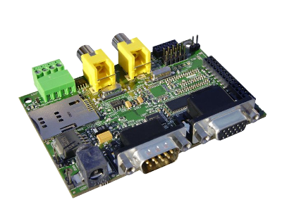
The IGEPv2 Expansion connects to the IGEPv2 Board through J990, JA41, JA42, JC30 and J960 connectors. Some IGEPv2 Expansion may include three jumpers, you should remove it because they are designed for test and lab purposes. Just take a look on the figure below to mount it:
 |
 |
TFT and Touchscreen
Basic

Know more
IGEPv2 Expansion integrates LCD backlight driver (TPS61081) and touch screen controller (TSC2046), a 4-wire touch screen controller which supports a low voltage I/O interface from 1.5V to 5.25V.
Serial port
Basic
IGEPv2 Expansion integrates a DB9 RS232 connector. Plug a DB9 cable.
Know more
This peripheral (UART 3) can be used to debug system using kernel traces, getting a remote prompt, etc.
VGA monitor
Basic

|

|
IGEPv2 Expansion integrates a VGA connector, the output VGA signal is equal to HDMI connector. Plug a monitor with VGA input.
Know more
This output is controled by ADV7125KSTZ140 Integrated Circuit.
CAN bus
Basic

Know more
This output is controled by MICROCHIP MCP2515. J703 is a 3.5 mm pitch terminal blocks 4 Positions:
| Signal Name | Pin # |
Description |
| VDD_CAN | J703:1 | Supply Voltage (+5V DC) |
| CANL | J703:2 | CAN Low-Level Voltage I/O |
| GND | J703:3 | Ground |
| CANH | J703:4 | CAN High-Level Voltage I/O |
GSM/GPRS modem
Basic

|
 |
| GSM-GPRS antenna (highly recommended) | SIM card reader |
IGEPv2 Expansion integrates a GSM/GPRS modem to make phone calls or to send SMS or to write and read data from it, etc.
Know more Modem chip Telit GE865 is a small GSM/GPRS Ball-Grid-Array BGA module with next main features:
- Quad-band EGSM 850 / 900 / 1800 / 1900 MHz
- Power consumption (typical values)
- Power off: ‹ 62 uA
- Idle (registered, power saving): 1.6 mA @ DRX=9
Composite Video Decoder
Basic

Know more
Analog input is decoded by TVP5151.
----
You have successfully completed this chapter of the guide.
|

|
If you have any question, don't ask to ask at the IGEP Community Forum or the IGEP Community Chat | 
|
|
|
What can i do with igepv2 expansion
|
|
Overview
This is the 2/3 chapter of IGEPv2 Expansion Tutorial Guide.
We will learn some basic tasks such add support to IGEPv2 Expansion, control some peripherals, etc.
What can I do
How to use Serial communication (DB9 connector)
Basic
RS232 link for UART 3 (/dev/ttyO2) can be obtained through J502 DB9 connector. You can use PuTTy to get a shell prompt to IGEP:
- Power up IGEPv2
- Open PuTTy.
- Choose Serial line. If you are running PuTTy on Windows, the Serial line will be like (COM1 or COM2 or COM3, etc.). If you are running PuTTy on Ubuntu, the Serial line will be like (/dev/ttyS0 or /dev/ttyS1 or /dev/ttyS3, etc.). Note that if you are using a USB->Serial converter, the Serial line will be like /dev/ttyUSB0
- Configure Speed to 115200
- Select Serial Connection type
- Press on Open button
- You will successfully started the console.

|

|
Know more
Read this tutorial to learn about UARTs.
How to use TFT and Touchscreen
Seiko a Powertip touch screens are not supported by default in IGEPv2. Use the following steps for it:
- Log into IGEPv2 (via SSH, as shown in the previous chapter), and run the following commands:
ssh root@192.168.5.1
mkdir /tmp/temp
mount -t jffs2 /dev/mtdblock1 /tmp/temp
vi /tmp/temp/igep.ini
- In Seiko screen add the following line:
omapdss.def_disp=lcd-70
- In Powertip screen add the following line:
omapdss.def_disp=lcd-43
- Save changes and reboot your IGEP Device to finish it.
How to use Telit Modem
Basic
Telit modem is not supported by default in IGEPv2. Use the following steps for it:
- Log into IGEPv2 (via SSH, as shown in the previous chapter), and run the following commands:
ssh root@192.168.5.1
mkdir /tmp/temp
mount -t jffs2 /dev/mtdblock1 /tmp/temp
vi /tmp/temp/igep.ini
- Add the following line (press i to insert content):
buddy.modem=yes
- Save changes (ESC -> :wq -> Enter) and reboot your IGEP Device
- Power up the modem. You can power off using again these commands:
echo 0 > /sys/class/gpio/gpio140/value
echo 1 > /sys/class/gpio/gpio141/value
sleep 1
echo 0 > /sys/class/gpio/gpio141/value
- Once the modem is on (led D401, near SIM card reader, is blinking now), you can interact with it via UART 2. You can use Microcom to comunicate with it from the serial debug console:
microcom -s 115200 /dev/ttyO1
- To check the modem status use the command:
at
- Answer should be OK.
- Now unlock it by inserting your SIM card PIN number. Use the command:
at+cpin=<PIN>
- If you correctly inserted the PIN number, the answer should be OK. If you fail more than 3 times, your SIM card will lock and you will have to insert PUK number.
- Now you are ready to use the GSM/GPS modem.
Examples
If you successfully followed the the previous instructions, you are ready to test the GSM/GPRS modem. Here are some examples:
You can check the complete list of AT commands at the Official manufacturer Software User Guide.
Test received signal strength
Use the instruction:
at+csq
The answer should be: +CSQ: X,0, where X is the signal strenght. For example 12 is poor and 18 is good. If the answer is +CSQ:99,99 you should check your coverage or use an antenna
Making a phone call
Use the instruction, replace number_to_call with your number:
atd number_to_call
Press any key to end call
NOTE: If "NO CARRIER" message appears, check your coverage or use an antenna.
Sending a SMS
First of all, you need to configure the SMS format type. Telit GE865 GSM/GPRS supports PDU format and Text format. We use Text format. Type the following command:
AT+CMGF=1
There are so many ways in this modem to send a message. Here you have a simple example. Use the instruction, replace destination_number with your number:
at+cmgs= destination_number
> insert here your text message
When you are ready to send your message use Ctrl+Z to send it.
If you want to cancel or restart the message press ESC.
NOTE: If "NO CARRIER" message appears, check your coverage or use an antenna.
NOTE: Don't use special characters in SMS text message like <`´'">.
Know more
Here you have the official manuals from the manufacturer's webpage:
How to use TVP5151 Video Decoder
Basic
Use the following steps to capture analog video:
- Connect a video composite input to J501 connector from IGEPv2 Expansion (near CAN Bus)
- Connect a screen, for example HDMI monitor.
- Log into IGEPv2 (via SSH, as shown in the previous chapter), and run the following commands:
ssh root@192.168.5.1
- Now you have a remote igep terminal
- Refresh repositories and accept it.
zypper ref
- Install video4linux2 plugin
zypper in gst-plugins-good-video4linux2
- Load OMAP ISP kernel module
modprobe omap3-isp
- Configure ISP, for PAL resulution use 720x576 for NTSC resolution use 720x480:
media-ctl -r -l '"tvp5150 2-005c":0->"OMAP3 ISP CCDC":0[1], "OMAP3 ISP CCDC":1->"OMAP3 ISP CCDC output":0[1]'
media-ctl -v --set-format '"tvp5150 2-005c":0 [UYVY 720x480]'
media-ctl -v --set-format '"OMAP3 ISP CCDC":0 [UYVY 720x480]'
media-ctl -v --set-format '"OMAP3 ISP CCDC":1 [UYVY 720x480]'
- Export display
export DISPLAY=:0.0
- Launch gstreamer
gst-launch-0.10 -v v4l2src device=/dev/video2 queue-size=8 ! video/x-raw-yuv,format=\(fourcc\)UYVY,width=720,height=480 ! ffmpegcolorspace ! autovideosink
- Now you can see in your IGEP screen a result similar like this

|
Know more
You can use other programs like yavta
How to use EEPROM
Basic
The IGEP0022 expansion board provides an AT24C01B serial EEPROM memory which is connected to the OMAP via I2C (register 50).
Use i2c-tools to manage it:
i2cget <bus> <chip> <register>
i2cset <bus> <chip> <register> <value>
For example, the following writes the value 0x22 to register 0x10 of device 0x50 on i2c bus 2:
i2cset -f -y 2 0x50 0x10 0x22
i2cget -f -y 2 0x50 0x10
Know more
See also: i2dump(8), i2cget(8) and i2cset(8) man page
How to use CAN bus (under construction)
You have to connect the two boards like this:
IGEPv2 1             IGEPv2 2
.---                 .---
| 1 |-X            X-| 1 |
| 2 |------------------| 2 |
| 3 |------------------| 3 |
| 4 |------------------| 4 |
.---                 .---
If this is your first time accessing CAN bus, check J702 jumper is not connected before follow this tutorial. If you don't have this jumper, don't worry because its function is only for testing.
Now you can set up the interface (on all boards when using multiple IGEPv2 EXPANSION connected to a CAN network simultaneously):
/bin/ip link set can0 up type can bitrate 125000
If you want to receive CAN data, use:
candump can0
If you want to send CAN data, use:
cansend can0 -i 0x123 0xaa 0xbb 0xcc 0xdd
On the receiver side, you must see the following messages:
can0 123 [4] aa bb cc dd
Switch roles and try it again
----
You have successfully completed this chapter of the guide.
|
|
|
If you have any question, don't ask to ask at the IGEP Community Forum or the IGEP Community Chat |
|