Difference between revisions of "User:Pau pajuelo"
From IGEP - ISEE Wiki
| Line 945: | Line 945: | ||
|Tech_ID={{#lst:Template:Links|IGEPv2_EXPANSION_Tech_ID}} | |Tech_ID={{#lst:Template:Links|IGEPv2_EXPANSION_Tech_ID}} | ||
|Name={{#lst:Template:Links|IGEPv2_EXPANSION_Name}} | |Name={{#lst:Template:Links|IGEPv2_EXPANSION_Name}} | ||
| − | |Image={{#lst:Template:Links| | + | |Image={{#lst:Template:Links|IGEPv2_EXPANSION_Image}} |
|ISEE_MainPage={{#lst:Template:Links|IGEPv2_EXPANSION_ISEE_MainPage}} | |ISEE_MainPage={{#lst:Template:Links|IGEPv2_EXPANSION_ISEE_MainPage}} | ||
|ISEE_Hardware={{#lst:Template:Links|IGEPv2_EXPANSION_ISEE_Hardware}} | |ISEE_Hardware={{#lst:Template:Links|IGEPv2_EXPANSION_ISEE_Hardware}} | ||
Revision as of 15:29, 7 August 2012
TODO:
Update peripheral tutorials
Categorize new tutorials
Upgrade ethernet gadget tutorial for new IGEP firmware and VM
Finish tutorials below
NOTES: Qt, Codeblocks and Eclipse are linked to main page:
Eclipse -> How to develop under Eclipse (copy manual) (refers at beginning VM and option to install Eclipse(under construction))
Qt -> How to develop under Qt (refers at begginin VM and option to install Qt (under construction))
Codeblocks (do it)
Adapt IGEPv2 to IGEPv2 Expansion
How to use SPI (prove with new firmware, under construction)
Overview
This How-To is meant to be a starting point for people to learn use SPI for IGEP devices as quickly and easily as possible. In this how-to, we run an example program that reads and writes registers from 3-axis accelerometer (LIS3DH) included on the board IGEP New York.
Requirements
There are some requisites to follow this guide:
- IGEP SDK VM: follow the IGEP SDK SOFTWARE USER MANUAL (chapter 2.3 "Setting up and running the VM")
- IGEP Firmware: follow the IGEP SDK SOFTWARE USER MANUAL (chapter 6.1 "Create IGEP firmware bootable micro-sd card")
- IGEP COM MODULE and IGEP NEW YORK
- SPI example program (link program)
- MicroSD Card (at least 2Gbytes)
How Works
LIS3DH accelerometer: It is the accelerometer mounted in IGEP New York.
Omap3 SPI Peripheral: It is the hardware used to communicated with accelerometer and other SPI devices.
Omap2_mcspi: It is a bus driver than controls Omap3 SPI Peripheral.
Spi: It is a protocol driver that defines functions and strucs used in SPI bus.
Spidev: It is a device driver that export spi driver functionalities to userspace.
Lis3lv02d_spi: SPI glue layer for lis3lv02d
Lis31v02d: Device driver for LIS3DH accelerometer.
Exp_ilms0015: It is a startup program for IGEP New York. It attach lis31v02d with Spi driver.

|
More information about Linux Kernel SPI at:
Prepare Micro SD Card
Generate Micro SD Card
Open a terminal and use the following steps to download and generate a Micro SD card.
wget http://downloads.isee.biz/denzil/binary/igep_firmware-yocto-1.2.1-1.tar.bz2
tar jxf igep_firmware-yocto-*.tar.bz2
cd igep_firmware-yocto-*
Insert a SD-Card media and use the igep-media-create script to copy the firmware.
./igep-media-create -–mmc <mmc> --image demo-image-sato-igep00x0.tar.bz2 --machine igep0030
where <mmc> - is the SD-Card device of your computer. For example, assuming the SD-card device takes '/dev/sdb' type:
./igep-media-create --mmc /dev/sdb --machine igep0030 --image demo-image-sato-igep00x0.tar.bz2
This should give you a bootable SD-card with IGEP COM MODULE support.
NOTE: Use the following tutorial (upgrade it) to connect via Ethernet Gadget with IGEP COM MODULE
Custom Micro SD Card
"Include clone git commands"
Modify Linux Kernel Sources to attach Spidev to SPI driver
To read accelerometer registers from spidev, we need to attach spidev driver to spi driver at start up. So it is necessary to modify spi_board.
Go to $(Kernel path)/arch/arm/mach-omap2/exp-ilms0015.c and edit the next fields in bold words.
|
static struct spi_board_info lis3lv02d_spi_board_info __initdata = { .modalias = "spidev", //.modalias = "lis3lv02d_spi", .bus_num = -EINVAL, .chip_select = -EINVAL, .max_speed_hz = 1*1000*1000, .irq = -EINVAL, .mode = SPI_MODE_0, //.platform_data = &lis3lv02d_pdata, }; inline void __init ilms0015_lis3lv02d_init(int bus_num, int cs, int irq) { struct spi_board_info *spi = &lis3lv02d_spi_board_info; if ((gpio_request(irq, "LIS3LV02D IRQ") == 0) && (gpio_direction_input(irq) == 0)) gpio_export(irq, 0); else { pr_err("IGEP: Could not obtain gpio LIS3LV02D IRQ\n"); return; } spi->bus_num = bus_num; spi->chip_select = cs; spi->irq = OMAP_GPIO_IRQ(irq), spi_register_board_info(&lis3lv02d_spi_board_info, 1); } ... void __init ilms0015_init(void) { mux_partition = omap_mux_get("core"); /* Mux initialitzation for ilms0015 */ omap_mux_write_array(mux_partition, ilms0015_mux); /* 3-axis accelerometer */ ilms0015_lis3lv02d_init(1, 2, 174); /* Export some GPIO */ ilms0015_gpio_init(); } |
Now spi_register_board_info has all information necessary to attach spidev driver instead lis3lv02d_spi.
Once we edit code, compile your modified Kernel, you can follow this tutorial for this purpose.
Enable ilms0015 support
“ilms0015” is the technical name of IGEP New York.
By default, poky-media-create (See: Poky firmware with Kernel 2.6.37.y) configured as igep0030, gives support only for IGEP Expansions Paris and Berlin. We need to configure igep.ini and gives support to IGEP New York:
| ; Machine configuration
;buddy=base0010 buddy.revision=B buddy=ilms0015 |
Test changes
Once you copy your new Kernel binaries and edit igep.ini. Power up your board, log in and check your changes:
|
root@igep00x0:/dev# lsmod Module Size Used by rfcomm 48522 0 hidp 13311 0 l2cap 49001 4 rfcomm,hidp bluetooth 67643 3 rfcomm,hidp,l2cap libertas_sdio 13887 0 libertas 99318 1 libertas_sdio option 13044 0 usb_wwan 7196 1 option usbserial 23870 2 option,usb_wwan spidev 4898 0 root@igep00x0:/dev# ls /dev/spidev1.2 /dev/spidev1.2 |
“spidev1.2”: refers at McSPI1 bus 2. Now we can communicate to accelerometer using spi driver functions.
SPI Test program
Overview
This program is based in spidev_test and it was edited to run with LIS3DH accelerometer, program can be explained in four parts:
Connection properties: program lets change via parameters SPI configurations like: device, max speed, delay, bits per word, clock phase, clock polarity, etc. If you don't use any of this parameters program will use default options for LIS3DH communication.
Read mode: Reads a word from a register.
Write mode: Writes a word in a register.
Test mode: Reads X, Y and Z axes from accelerometer.
We recommend to read peripheral datasheet before use or modify program.
Compile program
The program source was compiled with Poky SDK but you can use other compilers like Linaro Toolchain:
arm-poky-linux-gnueabi-gcc spiexamplebeta2.c -o spiexampleb2
Copy your final binary to rootfs.
Test program
Read WHO_AM_I register(0Fh)
LIS3DH has this dummy register (See 8.6 chapter) as a device identification. Its value is 0x33:
root@igep00x0:~# ./spiexampleb2 -R 0F
spi mode: 0
bits per word: 8
max speed: 1000000 Hz (1000 KHz)
Value from 0F is: 33
root@igep00x0:~#
Read and Write CTRL_REG1 (20h)
This register is used to enable/disable: accelerometer and XYZ axes (See 8.8 chapter). The default value at startup is:
root@igep00x0:~# ./spiexampleb2 -R 20
spi mode: 0
bits per word: 8
max speed: 1000000 Hz (1000 KHz)
Value from 20 is: 07
root@igep00x0:~#
It means that accelerometer was disabled and X, Y and Z axes was enabled. For example we can disable X axe typing:
root@igep00x0:~# ./spiexampleb2 -W 20 -V 06
spi mode: 0
bits per word: 8
max speed: 1000000 Hz (1000 KHz)
Register to write 20 with value 06
root@igep00x0:~# ./spiexampleb2 -R 20
spi mode: 0
bits per word: 8
max speed: 1000000 Hz (1000 KHz)
Value from 20 is: 06
root@igep00x0:~#
Read accelerometer axes
| Finally we are going to read gravity force: LIS3DH has ±2g/±4g/±8g/±16g dynamically selectable full scale (See chapter 8.11). The axes values are expressed in two’s complement in 16 bits (See chapters 8.16, 8.17 and 8.18). | 
|
root@igep00x0:~# ./spiexampleb2 -T
spi mode: 0
bits per word: 8
max speed: 1000000 Hz (1000 KHz)
Accelerometer TEST
Values from X -64, Values from Y -15872 and Values from Z -256
root@igep00x0:~#
The next table shows results at different positions:
| Position | ±2g scale | ±4g scale | ±8g scale | ±16g scale |
 |
X = 832
Y = 1024 Z = 15680 |
X = 256 Y = 128 Z = 7872 |
X = 128 Y = 128 Z = 4032 |
X = 64 Y = 128 Z = 1280 |
 |
X = 256 Y = 704 Z = -17216 |
X = 256 Y = 256 Z = -8320 |
X = 64 Y = 128 Z = -4096 |
X = 128 Y = 128 Z = -1344 |
 |
X = -15872 Y = 64 Z = -320 |
X = -7936 Y = 64 Z = -512 |
X = -3968 Y = 128 Z = -192 |
X = -1280 Y = 64 Z = -128 |
 |
X = 16448 Y = 640 Z = 640 |
X = 8128 Y = 192 Z = 384 |
X = 4032 Y = 64 Z = 64 |
X = 1344 Y = 64 Z = 192 |
 |
X = 896 Y = 16512 Z = -576 |
X = 320 Y = 8128 Z = -128 |
X = 192 Y = 4096 Z = -64 |
X = 128 Y = 1344 Z = -128 |
 |
X = -64 Y = -15872 Z = -256 |
X = -512 Y = -7808 Z = -384 |
X = -64 >Y = -3840 Z = -384 |
X = -128 Y = -1216 Z = -128 |
BACKUP How to use SPI (prove with new firmware, under construction)
Overview
This How-To is meant to be a starting point for people to learn use SPI for IGEP devices as quickly and easily as possible. In this how-to, we run an example program that reads and writes registers from 3-axis accelerometer (LIS3DH) included on the board IGEP New York.
Requirements
There are some requisites to follow this guide:
- IGEP SDK VM: follow the IGEP SDK SOFTWARE USER MANUAL (chapter 2.3 "Setting up and running the VM")
- IGEP Firmware: follow the IGEP SDK SOFTWARE USER MANUAL (chapter 6.1 "Create IGEP firmware bootable micro-sd card")
- IGEP COM MODULE and IGEP NEW YORK
- SPI example program (link program)
- MicroSD Card (at least 2Gbytes)
How Works
LIS3DH accelerometer: It is the accelerometer mounted in IGEP New York.
Omap3 SPI Peripheral: It is the hardware used to communicated with accelerometer and other SPI devices.
Omap2_mcspi: It is a bus driver than controls Omap3 SPI Peripheral.
Spi: It is a protocol driver that defines functions and strucs used in SPI bus.
Spidev: It is a device driver that export spi driver functionalities to userspace.
Lis3lv02d_spi: SPI glue layer for lis3lv02d
Lis31v02d: Device driver for LIS3DH accelerometer.
Exp_ilms0015: It is a startup program for IGEP New York. It attach lis31v02d with Spi driver.
|
|
More information about Linux Kernel SPI at:
Attach Spidev to SPI driver
Modify Linux Kernel Sources
To read accelerometer registers from spidev, we need to attach spidev driver to spi driver at start up. So it is necessary to modify spi_board.
Go to $(Kernel path)/arch/arm/mach-omap2/exp-ilms0015.c and edit the next fields in bold words.
|
static struct spi_board_info lis3lv02d_spi_board_info __initdata = { .modalias = "spidev", //.modalias = "lis3lv02d_spi", .bus_num = -EINVAL, .chip_select = -EINVAL, .max_speed_hz = 1*1000*1000, .irq = -EINVAL, .mode = SPI_MODE_0, //.platform_data = &lis3lv02d_pdata, }; inline void __init ilms0015_lis3lv02d_init(int bus_num, int cs, int irq) { struct spi_board_info *spi = &lis3lv02d_spi_board_info; if ((gpio_request(irq, "LIS3LV02D IRQ") == 0) && (gpio_direction_input(irq) == 0)) gpio_export(irq, 0); else { pr_err("IGEP: Could not obtain gpio LIS3LV02D IRQ\n"); return; } spi->bus_num = bus_num; spi->chip_select = cs; spi->irq = OMAP_GPIO_IRQ(irq), spi_register_board_info(&lis3lv02d_spi_board_info, 1); } ... void __init ilms0015_init(void) { mux_partition = omap_mux_get("core"); /* Mux initialitzation for ilms0015 */ omap_mux_write_array(mux_partition, ilms0015_mux); /* 3-axis accelerometer */ ilms0015_lis3lv02d_init(1, 2, 174); /* Export some GPIO */ ilms0015_gpio_init(); } |
Now spi_register_board_info has all information necessary to attach spidev driver instead lis3lv02d_spi.
Once we edit code, compile your modified Kernel, you can follow this tutorial for this purpose.
Enable ilms0015 support
“ilms0015” is the technical name of IGEP New York.
By default, poky-media-create (See: Poky firmware with Kernel 2.6.37.y) configured as igep0030, gives support only for IGEP Expansions Paris and Berlin. We need to configure igep.ini and gives support to IGEP New York:
| ; Machine configuration
;buddy=base0010 buddy.revision=B buddy=ilms0015 |
Test changes
Once you copy your new Kernel binaries and edit igep.ini. Power up your board, log in and check your changes:
|
root@igep00x0:/dev# lsmod Module Size Used by rfcomm 48522 0 hidp 13311 0 l2cap 49001 4 rfcomm,hidp bluetooth 67643 3 rfcomm,hidp,l2cap libertas_sdio 13887 0 libertas 99318 1 libertas_sdio option 13044 0 usb_wwan 7196 1 option usbserial 23870 2 option,usb_wwan spidev 4898 0 root@igep00x0:/dev# ls /dev/spidev1.2 /dev/spidev1.2 |
“spidev1.2”: refers at McSPI1 bus 2. Now we can communicate to accelerometer using spi driver functions.
SPI Test program
Overview
This program is based in spidev_test and it was edited to run with LIS3DH accelerometer, program can be explained in four parts:
Connection properties: program lets change via parameters SPI configurations like: device, max speed, delay, bits per word, clock phase, clock polarity, etc. If you don't use any of this parameters program will use default options for LIS3DH communication.
Read mode: Reads a word from a register.
Write mode: Writes a word in a register.
Test mode: Reads X, Y and Z axes from accelerometer.
We recommend to read peripheral datasheet before use or modify program.
Compile program
The program source was compiled with Poky SDK but you can use other compilers like Linaro Toolchain:
arm-poky-linux-gnueabi-gcc spiexamplebeta2.c -o spiexampleb2
Copy your final binary to rootfs.
Test program
Read WHO_AM_I register(0Fh)
LIS3DH has this dummy register (See 8.6 chapter) as a device identification. Its value is 0x33:
root@igep00x0:~# ./spiexampleb2 -R 0F
spi mode: 0
bits per word: 8
max speed: 1000000 Hz (1000 KHz)
Value from 0F is: 33
root@igep00x0:~#
Read and Write CTRL_REG1 (20h)
This register is used to enable/disable: accelerometer and XYZ axes (See 8.8 chapter). The default value at startup is:
root@igep00x0:~# ./spiexampleb2 -R 20
spi mode: 0
bits per word: 8
max speed: 1000000 Hz (1000 KHz)
Value from 20 is: 07
root@igep00x0:~#
It means that accelerometer was disabled and X, Y and Z axes was enabled. For example we can disable X axe typing:
root@igep00x0:~# ./spiexampleb2 -W 20 -V 06
spi mode: 0
bits per word: 8
max speed: 1000000 Hz (1000 KHz)
Register to write 20 with value 06
root@igep00x0:~# ./spiexampleb2 -R 20
spi mode: 0
bits per word: 8
max speed: 1000000 Hz (1000 KHz)
Value from 20 is: 06
root@igep00x0:~#
Read accelerometer axes
| Finally we are going to read gravity force: LIS3DH has ±2g/±4g/±8g/±16g dynamically selectable full scale (See chapter 8.11). The axes values are expressed in two’s complement in 16 bits (See chapters 8.16, 8.17 and 8.18). |
|
root@igep00x0:~# ./spiexampleb2 -T
spi mode: 0
bits per word: 8
max speed: 1000000 Hz (1000 KHz)
Accelerometer TEST
Values from X -64, Values from Y -15872 and Values from Z -256
root@igep00x0:~#
The next table shows results at different positions:
| Position | ±2g scale | ±4g scale | ±8g scale | ±16g scale |
| |
X = 832
Y = 1024 Z = 15680 |
X = 256 Y = 128 Z = 7872 |
X = 128 Y = 128 Z = 4032 |
X = 64 Y = 128 Z = 1280 |
| |
X = 256 Y = 704 Z = -17216 |
X = 256 Y = 256 Z = -8320 |
X = 64 Y = 128 Z = -4096 |
X = 128 Y = 128 Z = -1344 |
| |
X = -15872 Y = 64 Z = -320 |
X = -7936 Y = 64 Z = -512 |
X = -3968 Y = 128 Z = -192 |
X = -1280 Y = 64 Z = -128 |
| |
X = 16448 Y = 640 Z = 640 |
X = 8128 Y = 192 Z = 384 |
X = 4032 Y = 64 Z = 64 |
X = 1344 Y = 64 Z = 192 |
| |
X = 896 Y = 16512 Z = -576 |
X = 320 Y = 8128 Z = -128 |
X = 192 Y = 4096 Z = -64 |
X = 128 Y = 1344 Z = -128 |
| |
X = -64 Y = -15872 Z = -256 |
X = -512 Y = -7808 Z = -384 |
X = -64 >Y = -3840 Z = -384 |
X = -128 Y = -1216 Z = -128 |
How to install Qt Creator (under construction)
How to install Eclipse (under construction)
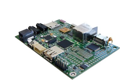
New igepv2 expansion getting started
|
|
Contents
- 1 TODO:
- 2 How to use SPI (prove with new firmware, under construction)
- 3 BACKUP How to use SPI (prove with new firmware, under construction)
- 4 How to install Qt Creator (under construction)
- 5 How to install Eclipse (under construction)
- 6 Overview
- 7 Requirements
- 8 Getting started
Overview
This is the 1/3 chapter of IGEPv2 Tutorial Guide.
In this first chapter, we will learn how to connect some peripherals, how to boot IGEPv2 and how to log into IGEPv2 via Ethernet.
Requirements
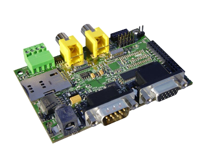
In this tutorial we are going to use the following peripherals:
- IGEPv2 with its power supply
- a monitor compatible with DVI-D
- a network cable.
- a USB keyboard and a mouse
- a PC with Linux or Windows
Getting started
Connect a DVI monitor
Basic
IGEPv2 has a HDMI connector with a DVI-D interface
Connect IGEPv2 to a DVI-D compatible monitor.
Know more
The Digital Visual Interface (DVI) is a video standard interface designed to provide very high visual quality on digital display devices such as flat panel LCD computer displays and digital projectors. It is partially compatible with the High-Definition Multimedia Interface (HDMI) standard in digital mode (DVI-D), and VGA in analog mode (DVI-A).
Note that your monitor should be able to support 1024 x 768 @ 60 Hz, which is the default resolution in the preinstalled software.
Connect an Ethernet Network cable
Basic
Plug an Ethernet cable between IGEPv2 and your client machine (or any other network device with ethernet connectivity).
Know more
IGEPv2 comes with one 10/100BASE-TX Ethernet ports.
In the following chapters we will use ethernet to access IGEPv2 with IP configuration, send files, etc.
Connect USB devices (keyboard and mouse)
Basic
Connect a USB hub to the USB type-A connector (USB Host) in IGEPv2.
Then plug a USB keyboard and USB mouse to the USB hub.
Know more
Only USB 2.0 devices will work in IGEPv2, so if you connect any USB mouse 1.0 into the USB host connector without using a USB hub 2.0, it will not work.
Power up IGEPv2 (5V DC)
Basic
Once you have connected the peripherals you can apply power to your IGEPv2 (5V DCC).
Know more
Led's sequence
When you power up your board, you will also see how two red LED's light up while the system boots (the sequence will be different based on software version). After a few seconds, there is a fixed green led on.
Boot priority
IGEPv2 can boot from many other devices (listed by priority):
- from USB
- from UART3
- from a MMC/MicroSD card
- from OneNAND memory
As we haven't set any other boot device rather than the oneNAND (the IGEPv2 flash memory) the system boots from it.
But, for example, if as the MicroSD card has an upper priority than the flash, if you plug a MicroSD card into IGEPv2 (with the right configuration on it), it will boot from the MicroSD card.
Test the Demo software distribution
Basic
When IGEPv2 powers up, the desktop of the preinstalled software will appear on the screen.
You can use the mouse and the keyboard to test the demo applications.

Know more
All IGEP Processor Boards, including IGEPv2, have a pre-installed software in its flash memory which consists of a minimal Linux-based distribution with a lite X Window System and GNOME Mobile based applications created with Poky Platform Builder.
In the next chapter of this tutorial guide, we will learn how to update the pre-installed software of your board.
Log into IGEPv2 via Ethernet interface
Basic
You can log into IGEPv2 via many interfaces, such Serial, Wifi, USB-Ethernet Gadget, etc.
In this tutorial we are going to connect to the board via its Ethernet interface.
By default, all IGEP Processor boards have a static IP in their Ethernet interface which is 192.168.5.1
First of all, adjust the IP of your PC in order to be in the right subnet of IGEPv2, for example: 192.168.5.10
Linux:
If you are running Linux in your PC, open a Terminal session and set the IP of the Ethernet interface in which IGEPv2 is connected (for example eth0):
Run the following commands:
sudo ifconfig eth0 192.168.5.10 up
Windows:
If you are running Windows in your PC, depending of your OS version and your configuration the steps might be slightly different:
- Click the Start button and select the Control Panel
- Go to Network configuration
- Right click the interface where IGEPv2 is connected (for example: Local Network) and select Propierties
- Select the TCP/IP Internet Protocol configuration and click the Propierties button
- Set a static IP (192.168.5.10) and 255.255.255.0 as network submask
- Close all the dialogs
Now you are ready to log into IGEPv2 via its Ethernet interface. You just need a program with a SSH client.
In this tutorial we are going to use Putty, as it is a multi-platform program.
You can download it from its official page at:
http://www.chiark.greenend.org.uk/~sgtatham/putty/download.html
Install and run Putty. It will look like this:

Follow these steps to connect to IGEPv2:
- Select the SSH at connection type.
- Insert the IP address of the target (IGEPv2 default IP: 192.168.5.1)
- Ensure that the port is set to 22, the default for SSH communications.
- Finally, press the Open button to start the SSH session.
If everything goes right, you will be able to access to an IGEPv2 console from your PC via Ethernet.
To login IGEPv2 use:
user:root
password: (no password for this user: press return)
Know more
In the pre-installed software, the default configuration for all the network interfaces is:
- eth0 - 192.168.5.1
- eth0:0 - via dhcp
- wlan0 - 192.168.6.1
- usb0 - 192.168.7.1
By default, the IP of the Ethernet interface is 192.168.5.1
Once you are logged in, you can see which interfaces are up in IGEPv2.
In the SSH console, run:
ifconfig
It will list all the active network interfaces.
If you want to change, for example, eth0 you can use the following commands (if you do it now, it will close the SSH session, as it will change the Ethernet IP):
ifconfig eth0 < new IP >
In order to make permanent changes (save the configuration upon next start), you will have to edit the /etc/network/interfaces file in your IGEPv2.
You have successfully completed this chapter of the guide.
|

|
If you have any question, don't ask to ask at the IGEP Community Forum or the IGEP Community Chat | 
|