|
|
| Line 1: |
Line 1: |
| − | __NOTOC__
| + | {{Table/IGEP Technology Devices |
| − | | + | |Tech_Family={{#lst:Template:Links|IGEP_COM_MODULE_Tech_Family}} |
| − | {| cellspacing="0" cellpadding="5" border="1" align="center" width="100%" style="text-align: left;"
| + | |Tech_ID={{#lst:Template:Links|IGEP_COM_MODULE_Tech_ID}} |
| − | |- | |
| − | | bgcolor="#cccccc" |'''What can I do with IGEP0030''' | |
| − | |-
| |
| − | | If you have '''successfully completed the [[{{#lst:Template:Links|IGEP_COM_MODULE_Community_Guides_1}}|first chapter of this guide]]''', you can continue with this tutorial guide about IGEP COM MODULE.
| |
| − | |}
| |
| − | | |
| − | | |
| − | {{Navigation/IGEP Technology Guides
| |
| | |Name={{#lst:Template:Links|IGEP_COM_MODULE_Name}} | | |Name={{#lst:Template:Links|IGEP_COM_MODULE_Name}} |
| | |Image={{#lst:Template:Links|IGEP_COM_MODULE_Image}} | | |Image={{#lst:Template:Links|IGEP_COM_MODULE_Image}} |
| | |ISEE_MainPage={{#lst:Template:Links|IGEP_COM_MODULE_ISEE_MainPage}} | | |ISEE_MainPage={{#lst:Template:Links|IGEP_COM_MODULE_ISEE_MainPage}} |
| | |ISEE_Hardware={{#lst:Template:Links|IGEP_COM_MODULE_ISEE_Hardware}} | | |ISEE_Hardware={{#lst:Template:Links|IGEP_COM_MODULE_ISEE_Hardware}} |
| − | |Community_MainPage={{#lst:Template:Links|IGEP_COM_MODULE_Community_MainPage}}
| |
| − | |Community_Guides_1={{#lst:Template:Links|IGEP_COM_MODULE_Community_Guides_1}}
| |
| − | |Community_Guides_2={{#lst:Template:Links|IGEP_COM_MODULE_Community_Guides_2}}
| |
| | }} | | }} |
| | | | |
| | | | |
| − | {| cellspacing="0" cellpadding="5" border="1" align="center" style="text-align: left;"
| + | __TOC__ |
| − | |-
| |
| − | | bgcolor="#cccccc" colspan="3" | '''Overview'''
| |
| − | |-
| |
| − | | [[Image:{{#lst:Template:Links|IGEP_COM_MODULE_Image}}|250px|center|link={{#lst:Template:Links|IGEP_COM_MODULE_Community_MainPage}}]]
| |
| − | |-
| |
| − | |'''1) [[#Booting and setting up|Booting up IGEP0030]]'''
| |
| − | |-
| |
| − | |'''2) [[#Updating the pre-installed software|Updating the pre-installed software]]'''
| |
| − | |-
| |
| − | |'''3) [[#Flashing the software image|Flashing the latest firmware to the IGEP0020 flash memory]]'''
| |
| − | |-
| |
| − | |'''4) [[#Connect to IGEP0030 via network interfaces|Connect to IGEP0030 via network interfaces]]'''
| |
| − | |-
| |
| − | |'''5) [[#Basic instructions|Basic instructions]]'''
| |
| − | |-
| |
| − | |'''6) [[#Send a file between a PC and IGEP0030|Send a file between a PC and IGEP0030]]'''
| |
| − | |-
| |
| − | |'''7) [[#How to handle the gpio-LED's|Handle IGEP0020 LED's]]'''
| |
| − | |-
| |
| − | |'''8) [[#Mount a MicroSD card|Mount a MicroSD card]]'''
| |
| − | |-
| |
| − | |}
| |
| − | | |
| − | | |
| − | === Booting and setting up ===
| |
| − | ----
| |
| − | | |
| − | {| cellspacing="0" cellpadding="5" border="1" align="center" width="100%" style="text-align: left;"
| |
| − | |-
| |
| − | | bgcolor="#cccccc" |'''Pre-installed software'''
| |
| − | |-
| |
| − | |By default, '''all brand new IGEP Processor Boards have a firmware installed''' on its flash memory.
| |
| − | | |
| − | That means that if you power up your board it will run a Linux distribution provided and installed by ISEE.
| |
| − | |}
| |
| − | | |
| − | | |
| − | This distribution consists of a '''minimal Linux-based distribution''' with a lite X Window System and GNOME Mobile based applications created with '''Poky Platform Builder'''.
| |
| − | | |
| − | In the previous chapter of this tutorial, we have booted IGEP COM MODULE with its pre-installed software.
| |
| − | | |
| − | Once the board has booted up, you can log in into IGEP0030 via many interfaces. In the previous chapter of this tutorial we have used the USB Ethernet Gadget and the Wifi interface, but you can use many other interfaces when connecting IGEP COM MODULE to an IGEP Expansion Board.
| |
| − | | |
| − | '''Boot priority'''
| |
| − | | |
| − | In fact, IGEP COM MODULE can boot from many other devices (listed by priority):
| |
| − | | |
| − | # from USB
| |
| − | # from UART3
| |
| − | # from a MMC/MicroSD card
| |
| − | # from OneNAND memory
| |
| − | | |
| − | | |
| − | As we haven't set any other boot device rather than the oneNAND (the IGEP0030 flash memory) the system boots from it.
| |
| − | | |
| − | | |
| − | But, as '''the MicroSD card has an upper priority than the flash''', if you plug a MicroSD card (with the right configuration on it) to the MicroSD card reader, IGEP0030 will boot from it and won't boot from the flash memory.
| |
| − | | |
| − | | |
| − | Now, We are going to use this functionality to update your pre-installed software.
| |
| − | | |
| − | | |
| − | === Updating the pre-installed software ===
| |
| − | ----
| |
| − | | |
| − | {| cellspacing="0" cellpadding="5" border="1" align="center" width="100%" style="text-align: left;"
| |
| − | |-
| |
| − | | bgcolor="#cccccc" |'''Requirements - Overview'''
| |
| − | |-
| |
| − | | For this purpose, you will need:
| |
| − | | |
| − | * a '''microSD card'''
| |
| − | * a '''computer''' with microSD card reader (or with adapter)
| |
| − | * a '''GNU/Linux distribution installed''' on the computer (a Linux partition or a virtual machine on Windows)
| |
| − | ** the main reason is that Windows does not detect multiple partitions on a microSD card
| |
| − | |-
| |
| − | |1) '''Download the latest firmware''' into an external computer.
| |
| − | | |
| − | 2) '''Uncompress the downloaded file'''.
| |
| − | | |
| − | 3) '''Create a MicroSD card''' in your external computer.
| |
| − | | |
| − | 4) '''Plug the MicroSD card''' to IGEP COM MODULE and boot from it.
| |
| − | |}
| |
| − | | |
| − | | |
| − | We are now going to update the pre-installed software to the latest version.
| |
| − | | |
| − | {{#lst:How to create a SD-card with the latest software image|IGEP_COM_MODULE}}
| |
| − | | |
| − | 4) '''Plug the MicroSD card'''
| |
| − | | |
| − | Therefore, you are ready to try it. '''Plug the MicroSD card into IGEP COM MODULE''' and '''power up your board'''.
| |
| − | | |
| − | === Flashing the software image ===
| |
| − | ----
| |
| − | | |
| − | Now your IGEP COM MODULE has the latest firmware '''running from MicroSD card'''.
| |
| − | | |
| − | But you might want to write the firmware to the flash memory, so '''you won't need the MicroSD card when booting''' the board. So let's do it.
| |
| − | | |
| − | | |
| − | ''Note: The following process is assuming that your host PC is connected to IGEP0020 via USB Ethernet Gadget or via Wifi. If not, read the [[Getting Started with IGEP COM MODULE board|previous chapter of this tutorial]].''
| |
| − | | |
| − | | |
| − | Enter to IGEP COM MODULE using:
| |
| − | | |
| − | * root as login name
| |
| − | * an empty password
| |
| − | | |
| − | The software provided by ISEE has a script that flashes the content of your MicroSD Card to the flash memory in your IGEP COM MODULE.
| |
| − | | |
| − | You have to run this script, that is located at /opt/firmware directory. Open a Terminal and run:
| |
| − | | |
| − | cd /opt/firmware
| |
| − | ./flash.sh
| |
| − | | |
| − | This will last a few minutes. When it is ready, unplug the SD card from IGEP COM MODULE and reboot the board:
| |
| − | | |
| − | reboot
| |
| − | | |
| − | Enjoy the new firmware running from flash memory.
| |
| − | | |
| − | '''Other references''': [[Update_the_PRE-INSTALLED_software_image_to_a_current_release|'''update your pre-installed software image''']]
| |
| − | | |
| − | | |
| − | === Basic instructions ===
| |
| − | ----
| |
| − | | |
| − | {| cellspacing="0" cellpadding="5" border="1" align="center" width="100%" style="text-align: left;"
| |
| − | |-
| |
| − | | bgcolor="#cccccc" |'''Overview'''
| |
| − | |-
| |
| − | | Learn some Bash basic instructions in Linux (for newbies).
| |
| − |
| |
| − | 1) Create, edit, move and delete files
| |
| − | | |
| − | 2) Run a simple script
| |
| − | |}
| |
| − | | |
| − | IGEP COM MODULE is '''compatible with many Linux distributions'''. In this tutorial we are using Poky Linux, which is the pre-installed software from ISEE.
| |
| − | | |
| − | In case you are not familiar with Bash instructions, here comes some basic instructions to help you startup with the board.
| |
| − | | |
| − | First of all, '''log in to IGEP COM MODULE''' with a console from your host PC (via serial port or via SSH), as shown previous sections in this article. Remember the default settings:
| |
| − | | |
| − | login: root
| |
| − | password: (none: press return)
| |
| − | | |
| − | Once you are logged in IGEP COM MODULE, run the following commands:
| |
| − | | |
| − | cd /
| |
| − | ls
| |
| − | | |
| − | You have moved to the root directory, that is "/".
| |
| − | The instruction "ls" lists all the existing files and directories in the current "path".
| |
| − | | |
| − | Now let's go to the directory /home/root/ with:
| |
| − | | |
| − | cd /home/root/
| |
| − | | |
| − | You can always check at which directory you are with the instruction:
| |
| − | | |
| − | pwd
| |
| − | | |
| − | Most instructions include a 'help' option that can be accessed by inserting the parameter --help. Check out the help page of 'echo' instruction, for example:
| |
| − | | |
| − | echo --help
| |
| − | | |
| − | You can try the instruction by yourself and type:
| |
| − | | |
| − | echo Hello
| |
| | | | |
| − | You have sent the text "Hello" to the standard output, that is the console you are interacting with.
| + | = Overview = |
| | | | |
| − | But you can change and 'redirect' the output by using the character '>' :
| + | This is the 2/3 chapter of IGEP COM MODULE Tutorial Guide. |
| | | | |
| − | echo Hello world! > /home/root/name.file
| + | We will learn some basic tasks such to send a file between IGEP COM MODULE and your PC , handle the IGEP COM Leds, update the pre-installed software to the latest release, etc. |
| | | | |
| − | Now notice you have redirected the output to a file called name.file :
| + | = What can I do = |
| | + | == Handle the gpio-LED's == |
| | + | {{#lst:How to handle the gpio-LED|IGEP_COM_MODULE}} |
| | | | |
| − | ls
| + | {{Table/IGEP Technology Devices |
| − | | + | |Tech_Family={{#lst:Template:Links|IGEP_COM_MODULE_Tech_Family}} |
| − | You can append any file using '>>' instead of '>'.
| + | |Tech_ID={{#lst:Template:Links|IGEP_COM_MODULE_Tech_ID}} |
| − | You can print the content of the file to the standard output:
| |
| − | | |
| − | cat /home/root/name.file
| |
| − | | |
| − | '''Building a basic script'''
| |
| − | | |
| − | You can create a script that can run any instruction you want to use in Bash. The main advantage is that you do not have to compile the code, as is auto-interpereted by the system.
| |
| − | | |
| − | We are going to create a basic 'Hello World' script that is going to run the same command you have actually used before:
| |
| − | | |
| − | echo "echo > Hello world!" > /home/root/example.sh
| |
| − | cat example.sh
| |
| − | | |
| − | Now you have created a file called example.sh, but by default it has no execute permissions (x):
| |
| − | | |
| − | ls -la
| |
| − | | |
| − | We are going to add permission to the file by:
| |
| − | | |
| − | chmod a+x example.sh
| |
| − | ls -la
| |
| − | | |
| − | Now you can run the script:
| |
| − | | |
| − | ./example.sh
| |
| − | | |
| − | You can edit this file (example.sh) with 'vi', the pre-installed text editor in IGEP COM MODULE.
| |
| − | | |
| − | vi example.sh
| |
| − | | |
| − | Press ESC and:
| |
| − | | |
| − | * :q! , to exit without saving
| |
| − | * :w , to save
| |
| − | * :wq , to quit and save
| |
| − | * i , to insert text
| |
| − | | |
| − | '''Other simple & useful instructions'''
| |
| − | | |
| − | * mkdir
| |
| − | * rmdir
| |
| − | * find
| |
| − | * grep
| |
| − | | |
| − | You can stop any instruction by pressing CTRL+C
| |
| − | | |
| − | | |
| − | === Send a file between a PC and IGEP COM MODULE === | |
| − | ----
| |
| − | | |
| − | In a Linux host PC, you can '''use SCP (secure copy) via SSH to transfer files''' between IGEP COM MODULE and your host PC.
| |
| − | | |
| − | We are going to use the default settings in IGEP COM MODULE for USB Ethernet Gadget and Wifi.
| |
| − | | |
| − | ''Note: This section is assuming you have successfully followed the previous chapters in this tutorial''
| |
| − | | |
| − | Now let's transfer a file called original.file from your host PC to the directory /home/root/ in your IGEP COM MODULE.
| |
| − | | |
| − | In your Host PC open Terminal and type:
| |
| − | | |
| − | scp -r original.file root@<destination_IP>:/home/root/destination.file
| |
| − | | |
| − | where:
| |
| − | | |
| − | *destination_IP: 192.168.7.2 via USB Ethernet Gadget, 192.168.6.1 via Wifi
| |
| − | | |
| − |
| |
| − | You can repeat the process from the IGEP COM MODULE console, and transfer a file from IGEP COM MODULE to your Host PC.
| |
| − | | |
| − | | |
| − | === How to handle the gpio-LED's ===
| |
| − | ----
| |
| − | | |
| − | {| cellspacing="0" cellpadding="5" border="1" align="center" width="100%" style="text-align: left;"
| |
| − | |- | |
| − | | bgcolor="#cccccc" |'''Overview'''
| |
| − | |-
| |
| − | | Using IGEP COM MODULE LED's with the associated platform device at /sys/devices/platform/leds-gpio/leds/
| |
| − | |}
| |
| − | | |
| − | IGEP COM MODULE has many devices that can be controlled using '''simple instructions'''.
| |
| − | | |
| − | In this tutorial, we are going to use the '''4 LED's available in the board''', which probably is the most simple feature in the board, but sometimes you may want LED's to be a way of checking the status of some of your applications.
| |
| − | | |
| − | You can easily '''turn LED's on and off''' using the 'echo' instruction.
| |
| − | | |
| − | Log into IGEP COM MODULE (via serial port or via SSH, as shown before), and run the following commands to turn LED's on:
| |
| − | | |
| − | <pre>echo 1 > /sys/devices/platform/leds-gpio/leds/d210\:green/brightness
| |
| − | echo 1 > /sys/devices/platform/leds-gpio/leds/d210\:red/brightness
| |
| − | echo 1 > /sys/devices/platform/leds-gpio/leds/d440\:green/brightness
| |
| − | echo 1 > /sys/devices/platform/leds-gpio/leds/d440\:red/brightness
| |
| − | </pre>
| |
| − | You can turn them down using the same command and write '0' instead of '1'. (Note: read [[#Known issues|known issues]] below)<br>
| |
| − | | |
| − | If you want to trigger the leds you can enable this mode and select the trigger source (none by default) to: mmc0, mmc1, timer, heartbeat and default-on.<br>
| |
| − | | |
| − | To enable any of this modes you just have to change a parameter in the directory of the led you want to control. You can see all the possibilities using 'cat':<br>
| |
| − | <pre>$ cat /sys/devices/platform/leds-gpio/leds/d210\:green/trigger
| |
| − | | |
| − | none mmc0 mmc1 timer heartbeat [default-on]
| |
| − | </pre>
| |
| − | In the example above, we have checked the status of the trigger in led D240:green. Mode 'default-on' is selected.
| |
| − | | |
| − | To change it, for example, to the timer mode you can use 'echo':<br>
| |
| − | <pre>echo timer > /sys/devices/platform/leds-gpio/leds/d210\:green/trigger
| |
| − | </pre>
| |
| − | In this case, we have set the trigger to the 'timer' mode. Now you can set the time for what the led is ON and the time it is OFF using:<br>
| |
| − | <pre>echo 250 > /sys/devices/platform/leds-gpio/leds/d210\:green/delay_on
| |
| − | echo 750 > /sys/devices/platform/leds-gpio/leds/d210\:green/delay_off
| |
| − | </pre>
| |
| − | Now the selected led is configured with a timer consisting of 250 miliseconds ON and 750 miliseconds OFF.
| |
| − | | |
| − | === Mount a MicroSD card ===
| |
| − | ----
| |
| − | | |
| − | (Work in progress section!)
| |
| − | | |
| − | ==== Access to Generic FAT32 microSD ====
| |
| − | | |
| − | mount -t vfat /dev/mmcblk0 /mnt/tmp/
| |
| − | | |
| − | ==== Access to Generic USB Flash disk ====
| |
| − | | |
| − | mount -t vfat /dev/sda1 /mnt/tmp/
| |
| − | | |
| − | ==== Safety Remove microSD ====
| |
| − | | |
| − | umount /mnt/tmp
| |
| − | | |
| − | ==== Access to IGEP demo microSD ====
| |
| − | | |
| − | mount -t jffs2 /dev/mmcblk0 /mnt/tmp/
| |
| − | | |
| − | | |
| − | = How to use wireless =
| |
| − | | |
| − | * [[How to setup Marvell 88w8686 SDIO wifi]]
| |
| − | | |
| − | = How to use bluetooth =
| |
| − | | |
| − | * [[How to setup Marvell bluetooth]]
| |
| − | | |
| − | = Known issues =
| |
| − | | |
| − | *In the IGEP COM MODULE Revision E, the D440 Green LED does not turn off completely due to hardware configuration.
| |
| − | | |
| − | | |
| − | {{Navigation/IGEP Technology Devices Guides/Next Step
| |
| | |Name={{#lst:Template:Links|IGEP_COM_MODULE_Name}} | | |Name={{#lst:Template:Links|IGEP_COM_MODULE_Name}} |
| − | |Community_MainPage={{#lst:Template:Links|IGEP_COM_MODULE_Community_MainPage}} | + | |Image={{#lst:Template:Links|IGEP_COM_MODULE_Image}} |
| − | |Next_Step=Start developing under IGEP Technology | + | |ISEE_MainPage={{#lst:Template:Links|IGEP_COM_MODULE_ISEE_MainPage}} |
| | + | |ISEE_Hardware={{#lst:Template:Links|IGEP_COM_MODULE_ISEE_Hardware}} |
| | }} | | }} |
| | | | |
| | [[Category:IGEP Technology Devices Guides]] | | [[Category:IGEP Technology Devices Guides]] |
| − | [[Category:IGEP0030]]
| |
| − | [[Category:Work in progress]]
| |
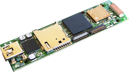
This is the 2/3 chapter of IGEP COM MODULE Tutorial Guide.
We will learn some basic tasks such to send a file between IGEP COM MODULE and your PC , handle the IGEP COM Leds, update the pre-installed software to the latest release, etc.
Log into IGEP COM MODULE (for example via SSH, as shown in the previous chapter), and run the following commands to turn LED's on:
You can turn them down using the same command and write '0' instead of '1'.
IGEP COM MODULE LED's are controlled with it's platform device at /sys/devices/platform/leds-gpio/leds/
If you want to trigger the leds you can enable this mode and select the trigger source (none by default) to: mmc0, mmc1, timer, heartbeat and default-on.
To enable any of this modes you just have to change a parameter in the directory of the led you want to control. You can see all the possibilities using the instruction 'cat':
In the example above, we have checked the status of the trigger in led D210:green. Mode 'none' is selected.
In this case, we have set the trigger to the 'timer' mode. Now you can set the time for what the led is ON and the time it is OFF using:
Now the selected led is configured with a timer consisting of 250 miliseconds ON and 750 miliseconds OFF.