


Difference between revisions of "What can I do with IGEP AQUILA EXPANSION"
From IGEP - ISEE Wiki
m |
m |
||
| (29 intermediate revisions by the same user not shown) | |||
| Line 1: | Line 1: | ||
| − | |||
| − | |||
{{Table/IGEP Technology Devices | {{Table/IGEP Technology Devices | ||
|Tech_Family={{#lst:Template:Links|IGEP_AQUILA_EXPANSION_Tech_Family}} | |Tech_Family={{#lst:Template:Links|IGEP_AQUILA_EXPANSION_Tech_Family}} | ||
| Line 13: | Line 11: | ||
= Overview = | = Overview = | ||
| − | This is the 2/3 chapter of the Getting Started with | + | This is the 2/3 chapter of the Getting Started with IGEP AQUILA EXPANSION Tutorial Guide. |
In this second chapter, we will learn some basics tasks. Upon completion, you will be ready to continue with chapter 3/3 that explains more advanced tasks. | In this second chapter, we will learn some basics tasks. Upon completion, you will be ready to continue with chapter 3/3 that explains more advanced tasks. | ||
| Line 19: | Line 17: | ||
__TOC__ | __TOC__ | ||
| − | |||
= What can I do = | = What can I do = | ||
| Line 25: | Line 22: | ||
You must logged in the board. | You must logged in the board. | ||
| − | == | + | == Remote connection via Ethernet == |
| − | + | {{Message/Information Message|title=|message=If you aren't using a Linux operating system, use [http://labs.isee.biz/index.php/IGEP_SDK_Virtual_Machine IGEP SDK Virtual Machine] to connect to the board}} | |
| − | + | In your Host Machine, open a terminal sessions set up an Ethernet alias for your network interface, | |
| − | |||
| − | |||
| − | + | $ sudo ifconfig eth0:0 192.168.5.10 | |
| − | + | Connect to the board using the SSH protocol | |
| − | + | $ ssh root@192.168.5.1 | |
| − | + | An empty password for root user should work to access to the shell prompt. | |
| − | + | ||
| + | == How to use audio HDMI == | ||
| − | + | IGEP COM AQUILA contains multiple I2S peripherals one of them is connected to HDMI transceiver. Then you can easily play a *.wav sound with the application Aplay, for example: | |
| − | + | <pre>aplay /opt/wav/test.wav</pre> | |
| − | |||
| − | + | == How to use LEDs == | |
| − | + | The board has three user leds available that can be controlled. In its simplest form, you can control of LEDs from | |
| + | userspace. LEDs appear in /sys/class/leds/ and you can turn on and off with following commands: | ||
A detailed guide on how use GPIO-LEDS can be found by following this link: [[How to handle the gpio-LED]] | A detailed guide on how use GPIO-LEDS can be found by following this link: [[How to handle the gpio-LED]] | ||
| + | === Control AQUILA COM Green LED === | ||
| + | |||
| + | <pre>echo "1" > /sys/class/leds/com\:green\:user/brightness</pre> | ||
| − | + | You can turn them down using the same command and write '0' instead of '1'. | |
| − | |||
| − | |||
| − | |||
| − | |||
| − | |||
| − | |||
| − | |||
| − | |||
| − | |||
| − | |||
| − | |||
| − | |||
| − | |||
| − | |||
| − | |||
| − | |||
| − | |||
| − | |||
| − | |||
| − | |||
| − | |||
| − | |||
| − | |||
| − | |||
| − | |||
| − | |||
| − | |||
| − | |||
| − | |||
| − | |||
| − | |||
| − | |||
| − | |||
| − | |||
| − | |||
| − | |||
| − | |||
| − | |||
| − | |||
| − | |||
| − | |||
| − | |||
| − | |||
| − | |||
| − | |||
| − | |||
| − | |||
| − | |||
| − | |||
| − | |||
| − | |||
| − | |||
| − | |||
| − | |||
| − | |||
| − | |||
| − | |||
| − | |||
| − | |||
| − | |||
| − | |||
| − | |||
| − | |||
| − | |||
| − | |||
| − | |||
| − | |||
| − | |||
| − | |||
| − | |||
| − | |||
| − | |||
| − | |||
| − | |||
| − | |||
| − | |||
| − | |||
| − | |||
| − | |||
| − | |||
| − | |||
| − | |||
| − | |||
| − | |||
| − | |||
| − | |||
| − | |||
| − | |||
| − | |||
| − | |||
| − | |||
| − | |||
| − | |||
| − | |||
| − | |||
| − | + | === Control AQUILA EXPANSION Bicolor LED === | |
| + | <pre>echo "1" > /sys/class/leds/base\:green\:user/brightness | ||
| + | echo "1" > /sys/class/leds/base\:red\:user/brightness</pre> | ||
| − | + | You can turn them down using the same command and write '0' instead of '1'. | |
| − | + | == How to use EEPROM == | |
| − | + | IGEP AQUILA EXPANSION contains a 32 Kb EEPROM. EEPROM can be read and write via /sys/devices/ocp.2/44e0b000.i2c/i2c-0/0-0050/eeprom: | |
| + | * Write EEPROM: | ||
| + | <pre>echo "data" > /sys/devices/ocp.2/44e0b000.i2c/i2c-0/0-0050/eeprom </pre> | ||
| + | * Read EEPROM: | ||
| + | <pre>cat /sys/devices/ocp.2/44e0b000.i2c/i2c-0/0-0050/eeprom</pre> | ||
| − | + | == How to use USB OTG == | |
| − | + | The base can be powered though USB OTG connector, but it's recommended use an external USB hub. Use an USB Standard-A to Mini-B type cable between the base and the USB hub and connect with: | |
| − | + | <pre>ssh root@192.168.7.1</pre> | |
| − | A detailed guide on how use | + | A detailed guide on how use Ethernet Gadget can be found by following this link: [[Using USB ethernet gadget to communicate]] |
{{Template:Navigation/IGEP Technology Guides/What can I do/Ending}} | {{Template:Navigation/IGEP Technology Guides/What can I do/Ending}} | ||
[[Category:IGEP Technology Devices Guides]] | [[Category:IGEP Technology Devices Guides]] | ||
Latest revision as of 12:26, 30 December 2013
|
|
Overview
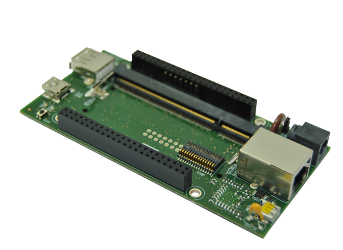
This is the 2/3 chapter of the Getting Started with IGEP AQUILA EXPANSION Tutorial Guide.
In this second chapter, we will learn some basics tasks. Upon completion, you will be ready to continue with chapter 3/3 that explains more advanced tasks.
Contents
What can I do
You must logged in the board.
Remote connection via Ethernet

|
If you aren't using a Linux operating system, use IGEP SDK Virtual Machine to connect to the board |
In your Host Machine, open a terminal sessions set up an Ethernet alias for your network interface,
$ sudo ifconfig eth0:0 192.168.5.10
Connect to the board using the SSH protocol
$ ssh root@192.168.5.1
An empty password for root user should work to access to the shell prompt.
How to use audio HDMI
IGEP COM AQUILA contains multiple I2S peripherals one of them is connected to HDMI transceiver. Then you can easily play a *.wav sound with the application Aplay, for example:
aplay /opt/wav/test.wav
How to use LEDs
The board has three user leds available that can be controlled. In its simplest form, you can control of LEDs from userspace. LEDs appear in /sys/class/leds/ and you can turn on and off with following commands:
A detailed guide on how use GPIO-LEDS can be found by following this link: How to handle the gpio-LED
Control AQUILA COM Green LED
echo "1" > /sys/class/leds/com\:green\:user/brightness
You can turn them down using the same command and write '0' instead of '1'.
Control AQUILA EXPANSION Bicolor LED
echo "1" > /sys/class/leds/base\:green\:user/brightness
echo "1" > /sys/class/leds/base\:red\:user/brightness
You can turn them down using the same command and write '0' instead of '1'.
How to use EEPROM
IGEP AQUILA EXPANSION contains a 32 Kb EEPROM. EEPROM can be read and write via /sys/devices/ocp.2/44e0b000.i2c/i2c-0/0-0050/eeprom:
- Write EEPROM:
echo "data" > /sys/devices/ocp.2/44e0b000.i2c/i2c-0/0-0050/eeprom
- Read EEPROM:
cat /sys/devices/ocp.2/44e0b000.i2c/i2c-0/0-0050/eeprom
How to use USB OTG
The base can be powered though USB OTG connector, but it's recommended use an external USB hub. Use an USB Standard-A to Mini-B type cable between the base and the USB hub and connect with:
ssh root@192.168.7.1
A detailed guide on how use Ethernet Gadget can be found by following this link: Using USB ethernet gadget to communicate
You have successfully completed this chapter of the guide.
|

|
If you have any question, don't ask to ask at the IGEP Community Forum or the IGEP Community Chat | 
|