|
|
| Line 44: |
Line 44: |
| | |} | | |} |
| | | | |
| − | == Serial port ==
| |
| | | | |
| − | '''Basic''' [[Image:Igepv2expdb9connector.PNG|right|200px]]
| |
| | | | |
| − | IGEPv2 Expansion integrates a DB9 RS232 connector. Plug a DB9 cable. <br>
| + | {{Navigation/IGEP Technology Guides/Getting Started/Ending |
| − | | |
| − | '''Know more'''
| |
| − | | |
| − | This peripheral (UART 3) can be used to debug system using kernel traces, getting a remote prompt, etc. <br> <br> <br>
| |
| − | | |
| − | == VGA monitor ==
| |
| − | | |
| − | '''Basic'''
| |
| − | | |
| − | {| cellspacing="1" cellpadding="1" width="363" border="1" align="right"
| |
| − | |-
| |
| − | | [[Image:Igepv2expconnecttovga.jpg|150px]]
| |
| − | | [[Image:Igepv2expvgaconnector.PNG|200px]]
| |
| − | |}
| |
| − | | |
| − | IGEPv2 Expansion integrates a VGA connector, the output VGA signal is equal to HDMI connector. Plug a monitor with VGA input.
| |
| − | | |
| − | '''Know more'''
| |
| − | | |
| − | This output is controled by ADV7125KSTZ140 Integrated Circuit.
| |
| − | | |
| − | <br> <br> <br><br> <br>
| |
| − | | |
| − | == CAN bus ==
| |
| − | | |
| − | '''Basic'''
| |
| − | | |
| − | [[Image:Igepv2expcanconnector.PNG|right|200px]]IGEPv2 Expansion integrates a CAN peripheral. Connect any CAN bus device or network to the CAN bus connector (J703).<br>
| |
| − | | |
| − | '''Know more'''
| |
| − | | |
| − | This output is controled by MICROCHIP MCP2515. J703 is a 3.5 mm pitch terminal blocks 4 Positions:
| |
| − | | |
| − | {| cellspacing="1" cellpadding="1" width="350" border="1"
| |
| − | |-
| |
| − | | Signal Name
| |
| − | | Pin #<br>
| |
| − | | Description
| |
| − | |-
| |
| − | | VDD_CAN
| |
| − | | J703:1
| |
| − | | Supply Voltage (+5V DC)
| |
| − | |-
| |
| − | | CANL
| |
| − | | J703:2
| |
| − | | CAN Low-Level Voltage I/O
| |
| − | |-
| |
| − | | GND
| |
| − | | J703:3
| |
| − | | Ground
| |
| − | |-
| |
| − | | CANH
| |
| − | | J703:4
| |
| − | | CAN High-Level Voltage I/O
| |
| − | |}
| |
| − | | |
| − | == GSM/GPRS modem ==
| |
| − | | |
| − | '''Basic'''
| |
| − | | |
| − | {| align="right" cellspacing="1" cellpadding="1" border="1" width="200"
| |
| − | |-
| |
| − | | [[Image:IGEP0022 Modem with antenna.png|200px]]
| |
| − | | [[Image:Igepv2expcardreader.PNG|right|200px]]
| |
| − | |-
| |
| − | | GSM-GPRS antenna (highly recommended)
| |
| − | | SIM card reader
| |
| − | |}
| |
| − | | |
| − | IGEPv2 Expansion integrates a GSM/GPRS modem to make phone calls or to send SMS or to write and read data from it, etc.<br>
| |
| − | | |
| − | '''Know more'''
| |
| − | | |
| − | Modem chip Telit GE865 is a small GSM/GPRS Ball-Grid-Array BGA module with next main features:
| |
| − | | |
| − | *Quad-band EGSM 850 / 900 / 1800 / 1900 MHz
| |
| − | *Power consumption (typical values)
| |
| − | | |
| − | - Power off: ‹ 62 uA<br> - Idle (registered, power saving): 1.6 mA @ DRX=9 <br> <br> <br>
| |
| − | | |
| − | == Composite Video Decoder ==
| |
| − | | |
| − | '''Basic'''
| |
| − | | |
| − | [[Image:Igepv2expvideocompositeconnector.PNG|right|200px]]IGEPv2 Expansion integrates two composite video connectors to decode analog input signal. Plug some peripheral with video composite output.<br>
| |
| − | | |
| − | '''Know more'''
| |
| − | | |
| − | Analog input is decoded by TVP5151.
| |
| − | | |
| − | <br> {{Navigation/IGEP Technology Guides/Getting Started/Ending
| |
| | |Next_Step={{#lst:Template:Links|IGEPv2_EXPANSION_Community_Guides_2}} | | |Next_Step={{#lst:Template:Links|IGEPv2_EXPANSION_Community_Guides_2}} |
| − | }}
| |
| − |
| |
| − | {{Table/IGEP Technology Devices
| |
| − | |Tech_Family={{#lst:Template:Links|IGEPv2_EXPANSION_Tech_Family}}
| |
| − | |Tech_ID={{#lst:Template:Links|IGEPv2_EXPANSION_Tech_ID}}
| |
| − | |Name={{#lst:Template:Links|IGEPv2_EXPANSION_Name}}
| |
| − | |Image={{#lst:Template:Links|IGEPv2_EXPANSION_Image}}
| |
| − | |ISEE_MainPage={{#lst:Template:Links|IGEPv2_EXPANSION_ISEE_MainPage}}
| |
| − | |ISEE_Hardware={{#lst:Template:Links|IGEPv2_EXPANSION_ISEE_Hardware}}
| |
| | }} | | }} |
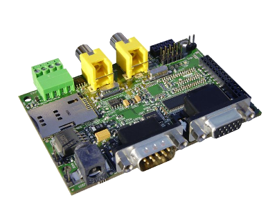
This is the 1/3 chapter of IGEPv2 Expansion Tutorial Guide.
In this first chapter, we will learn how to connect some expansion peripherals.
The IGEPv2 Expansion connects to the IGEPv2 Board through J990, JA41, JA42, JC30 and J960 connectors. Some IGEPv2 Expansion may include three jumpers, you should remove it because they are designed for test and lab purposes. Just take a look on the figure below to mount it: