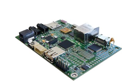
Difference between revisions of "Getting started with IGEPv2"
From IGEP - ISEE Wiki
(Created page with '__NOTOC__ {{Navigation/IGEP Technology Guides|device=IGEP0020}} {| cellspacing="0" cellpadding="5" border="1" align="center" width="100%" style="text-align: left;" |- | bgcolo…') |
|||
| (102 intermediate revisions by 5 users not shown) | |||
| Line 1: | Line 1: | ||
| − | + | {{Table/IGEP Technology Devices | |
| + | |Tech_Family={{#lst:Template:Links|IGEPv2_Tech_Family}} | ||
| + | |Tech_ID={{#lst:Template:Links|IGEPv2_Tech_ID}} | ||
| + | |Name={{#lst:Template:Links|IGEPv2_Name}} | ||
| + | |Image={{#lst:Template:Links|IGEPv2_Image}} | ||
| + | |ISEE_MainPage={{#lst:Template:Links|IGEPv2_ISEE_MainPage}} | ||
| + | |ISEE_Hardware={{#lst:Template:Links|IGEPv2_ISEE_Hardware}} | ||
| + | }} | ||
| − | |||
| + | __TOC__ | ||
| − | + | =Requirements= | |
| − | + | In this tutorial we are going to use the following peripherals: | |
| − | |||
| − | |||
| − | |||
| − | |||
| + | * IGEPv2 with its power supply | ||
| + | * Monitor compatible with DVI-D | ||
| + | * HDMI/DVI-D cable | ||
| + | * Network cable | ||
| + | * Powered USB HUB 2.0 | ||
| + | * USB keyboard and a mouse | ||
| + | * PC | ||
| − | + | =Getting started= | |
| − | + | The following video illustrates the getting started process. You will see how to connect some peripherals and power up the board. | |
| − | |||
| − | |||
| − | |||
| − | |||
| − | |||
| − | |||
| − | |||
| − | |||
| − | |||
| − | |||
| − | |||
| − | |||
| − | |||
| − | |||
| − | |||
| − | |||
| + | <div style="text-align: center;"> | ||
| + | {{#ev:youtube|jtHL6JVo7kA|500}} | ||
| + | </div> | ||
| + | ==Monitor== | ||
| + | The board will connect to your DVI monitor via its HDMI connector. You can use a HDMI/DVI-D cable to connect the board to the monitor. Your monitor should be able to support 1024 x 768 @ 60 Hz, which is the default resolution used by the firmware. | ||
| − | + | If your monitor doesn't have a DVI-D input, you can also use a HDMI input using a HDMI/HDMI cable, in that case you should [[How_do_I_edit_my_kernel_command_line | edit the kernel cmdline parameters]] and replace : | |
| + | omapfb.mode=dvi:1280x720MR-16@60 | ||
| − | + | for this one : | |
| − | |||
| − | |||
| − | + | omapfb.mode=dvi:hd720-16@60 | |
| − | + | ==Network== | |
| − | + | You may now plug the Ethernet cable into the 10/100 Ethernet jack of the board to get network access. The default firmware configures the Ethernet device with static ip address (192.168.5.1). | |
| − | |||
| − | |||
| − | + | ==Keyboard/Mouse== | |
| + | The USB Host of the board is ONLY USB High speed (480Mbit/s). You will need a powered USB hub 2.0 to connect to most USB devices. | ||
| + | Now, connect an USB hub to the USB Host and plug your keyboard and mouse into the hub. | ||
| − | + | ==Booting== | |
| − | + | With all the peripherals attached, plug in the wall adapter (5V DC) and power on your board. You will see a few lights flash, see how to red leds light up and after a few seconds may light up only a fixed green led. The sequence will be different based on software version. | |
| − | |||
| − | |||
| − | |||
| − | You will | ||
| − | |||
| − | + | "Under the hood" the bootloader is preparing to load the linux kernel. The linux kernel loads and initializes the hardware and mounts the root file system. Finally, you will see a screen desktop like the following screenshot. | |
| + | The pre-installed firmware in its flash memory consists of a minimal Linux-based distribution with a lite X Window System and GNOME Mobile based applications created with Poky Platform Builder. | ||
| − | + | You can use the mouse and the keyboard to dive into the desktop. | |
| + | [[Image:Poky-screenshot.png|thumb|center|500px|Screenshot of the Desktop of the pre-installed software]] | ||
| − | + | ==Remote connection via Ethernet== | |
| − | | | + | {{Message/Information Message|title=|message=If you aren't using a Linux operating system, use [http://labs.isee.biz/index.php/IGEP_SDK_Virtual_Machine IGEP SDK Virtual Machine] to connect to the board}} |
| − | | | ||
| − | |||
| − | |||
| − | |||
| − | In | + | In your Host Machine, open a terminal sessions set up an Ethernet alias for your network interface, |
| − | + | $ sudo ifconfig eth0:0 192.168.5.10 | |
| − | + | Connect to the board using the SSH protocol | |
| − | + | $ ssh root@192.168.5.1 | |
| − | + | An empty password for root user should work to access to the shell prompt. | |
| − | + | {{Navigation/IGEP Technology Guides/Getting Started/Ending | |
| + | |Next_Step={{#lst:Template:Links|IGEPv2_Community_Guides_2}} | ||
| + | }} | ||
| − | + | [[Category:IGEP Technology Devices Guides]] | |
| − | |||
| − | |||
| − | |||
| − | |||
| − | |||
| − | |||
| − | |||
| − | |||
| − | |||
| − | |||
| − | |||
| − | |||
| − | |||
| − | |||
| − | |||
| − | |||
| − | |||
| − | |||
| − | |||
| − | |||
| − | |||
| − | |||
| − | |||
| − | |||
| − | |||
| − | |||
| − | |||
| − | |||
| − | |||
| − | |||
| − | |||
| − | |||
| − | |||
| − | |||
| − | |||
| − | |||
| − | |||
| − | |||
| − | |||
| − | |||
| − | |||
| − | |||
| − | |||
| − | |||
| − | |||
| − | |||
| − | |||
| − | |||
| − | |||
| − | |||
| − | |||
| − | |||
| − | |||
| − | |||
| − | |||
| − | |||
| − | |||
| − | |||
| − | |||
| − | |||
| − | |||
| − | |||
| − | |||
| − | |||
Latest revision as of 10:10, 9 April 2018
|
|
Contents
Requirements
In this tutorial we are going to use the following peripherals:
- IGEPv2 with its power supply
- Monitor compatible with DVI-D
- HDMI/DVI-D cable
- Network cable
- Powered USB HUB 2.0
- USB keyboard and a mouse
- PC
Getting started
The following video illustrates the getting started process. You will see how to connect some peripherals and power up the board.
Monitor
The board will connect to your DVI monitor via its HDMI connector. You can use a HDMI/DVI-D cable to connect the board to the monitor. Your monitor should be able to support 1024 x 768 @ 60 Hz, which is the default resolution used by the firmware.
If your monitor doesn't have a DVI-D input, you can also use a HDMI input using a HDMI/HDMI cable, in that case you should edit the kernel cmdline parameters and replace :
omapfb.mode=dvi:1280x720MR-16@60
for this one :
omapfb.mode=dvi:hd720-16@60
Network
You may now plug the Ethernet cable into the 10/100 Ethernet jack of the board to get network access. The default firmware configures the Ethernet device with static ip address (192.168.5.1).
Keyboard/Mouse
The USB Host of the board is ONLY USB High speed (480Mbit/s). You will need a powered USB hub 2.0 to connect to most USB devices.
Now, connect an USB hub to the USB Host and plug your keyboard and mouse into the hub.
Booting
With all the peripherals attached, plug in the wall adapter (5V DC) and power on your board. You will see a few lights flash, see how to red leds light up and after a few seconds may light up only a fixed green led. The sequence will be different based on software version.
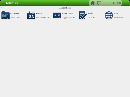
"Under the hood" the bootloader is preparing to load the linux kernel. The linux kernel loads and initializes the hardware and mounts the root file system. Finally, you will see a screen desktop like the following screenshot.
The pre-installed firmware in its flash memory consists of a minimal Linux-based distribution with a lite X Window System and GNOME Mobile based applications created with Poky Platform Builder.
You can use the mouse and the keyboard to dive into the desktop.
Remote connection via Ethernet

|
If you aren't using a Linux operating system, use IGEP SDK Virtual Machine to connect to the board |
In your Host Machine, open a terminal sessions set up an Ethernet alias for your network interface,
$ sudo ifconfig eth0:0 192.168.5.10
Connect to the board using the SSH protocol
$ ssh root@192.168.5.1
An empty password for root user should work to access to the shell prompt.
You have successfully completed this chapter of the guide.
|

|
If you have any question, don't ask to ask at the IGEP Community Forum or the IGEP Community Chat | 
|


