

Difference between revisions of "Getting started with IGEP SMARC EXPANSION"
From IGEP - ISEE Wiki
(→Overview) |
(→Requirements) |
||
| Line 34: | Line 34: | ||
* Network cable | * Network cable | ||
* PC | * PC | ||
| − | |||
| − | |||
| − | |||
| − | |||
| − | |||
| − | |||
| − | |||
| − | |||
| − | |||
| − | |||
| − | |||
| − | |||
| − | |||
| − | |||
| − | |||
| − | |||
| − | |||
| − | |||
| − | |||
| − | |||
| − | |||
| − | |||
| − | |||
| − | |||
| − | |||
Revision as of 11:50, 21 March 2017
|
|
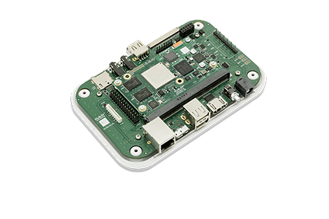
Overview
This is the 1/3 chapter of the Getting Started with IGEP AQUILA EXPANSION Tutorial Guide. In this first chapter, we will learn :
- Connect some peripherals, including monitor and USBs.
- Boot the board and touring the default firmware.
- Connect remotely to the board via Serial interface.
Upon completion, you will be ready to continue with chapter 2/3 that explains more advanced tasks.
Contents
Requirements
In this tutorial we are going to use the following peripherals:
- IGEP SMARC AM335x o iMX moudule with an uSD card
- IGEP SMARC EXPANSION with its power supply
- FTDI cable
- Monitor compatible with HDMI with audio.
- HDMI cable
- Powered USB HUB 2.0
- USB keyboard and a mouse
- Network cable
- PC