Difference between revisions of "Getting Started with IGEP0022 board"
From IGEP - ISEE Wiki
m |
|||
| Line 30: | Line 30: | ||
| − | == GSM/GPRS | + | == GSM/GPRS antenna == |
| + | |||
| + | Connect an external GSM/GPRS antenna to the J404 GSC connector. | ||
| + | |||
| + | [[Image:IGEP0022_Modem_with_antenna.png|497x309px]] | ||
== TFT and Touchscreen == | == TFT and Touchscreen == | ||
Revision as of 13:33, 7 July 2011
Contents
Overview
Important - Please read these documents before continuing with this article:
- Official IGEP0022 Hardware Reference Manual from ISEE
- Official IGEP0020 Hardware Reference Manual from ISEE
Mounting IGEP0022
The IGEP0022 expansion board connects to IGEP0020 via 5 connectors of 10, 22, 28 and 30 pins located on both boards. First align the biggest 28 pin-connector gently press it until the other four connectors insert into their corresponding connectors.
Adding peripherals
You can begin to add peripherals like Serial port, VGA monitor, CAN bus, a SIM card reader, TFT and Touchscreen and the S-Video connectors.
Serial port
VGA monitor
CAN bus
SIM card reader
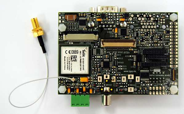
GSM/GPRS antenna
Connect an external GSM/GPRS antenna to the J404 GSC connector.
TFT and Touchscreen
S-Video connectors
How to enable IGEP0020 support
(ipeg.ini)


