Difference between revisions of "User:Crecasens"
From IGEP - ISEE Wiki
| (One intermediate revision by the same user not shown) | |||
| Line 91: | Line 91: | ||
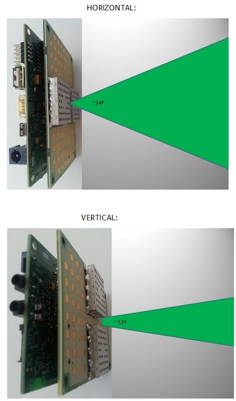
Be aware of the radar angle of detection. The radar will only detect objects within its field of view. The angle of detection is about 24º in horizontal direction and about 12º in vertical direction:<br> | Be aware of the radar angle of detection. The radar will only detect objects within its field of view. The angle of detection is about 24º in horizontal direction and about 12º in vertical direction:<br> | ||
| − | [[Image: | + | [[Image:FIELD OF VIEW.jpg]] |
=== Wait few minutes === | === Wait few minutes === | ||
| Line 229: | Line 229: | ||
Now you can move the radar and make measurements over the wall at two different distances. For example, make a measurement with the radar at 2m distance and another measurement with the radar at 5m distance. You should get similar results as the following for 2m and 5m in order:<br> | Now you can move the radar and make measurements over the wall at two different distances. For example, make a measurement with the radar at 2m distance and another measurement with the radar at 5m distance. You should get similar results as the following for 2m and 5m in order:<br> | ||
| − | + | [[Image:COMPARING_RADAR_MEASUREMENTS.jpg]] | |
| − | |||
| − | |||
| − | |||
| − | |||
| − | |||
| − | |||
| − | |||
| − | |||
| − | |||
| − | |||
| − | |||
| − | |||
| − | |||
| − | |||
It can be clearly shown how the IF radar signal increases frequency when the target gets more and more distance from the equipment. Look at the increment in periods (frequency) in the time domain signal, and the FFT peak has moved towards higher frequencies.<br> | It can be clearly shown how the IF radar signal increases frequency when the target gets more and more distance from the equipment. Look at the increment in periods (frequency) in the time domain signal, and the FFT peak has moved towards higher frequencies.<br> | ||
| − | |||
| − | |||
<br> | <br> | ||
Latest revision as of 12:51, 26 July 2013
Overview
This is the 1/3 chapter of the Getting Started with IGEP RADAR LAMBDA Tutorial Guide. In this first chapter, we will learn:
- Connect the radar to a PC via Ethernet.
- Boot the board with the default firmware.
- Make first measurements using web server demo application.
Upon completion, you will be ready to continue with chapter 2/3 that explains more advanced tasks.
Contents
Requirements
In this tutorial we are going to use the following materials:
- IGEP RADAR LAMBDA with its power supply
- Network cable
- PC with keyboard, mouse and monitor
Getting started
Please follow the next steps as indicated. You could change later the way you use the radar but it is very important you follow these instructions at least once for the first time. With this exercise you will start to understand how the radar works and most of your questions will be solved in a few minutes.
Identify your Radar
First of all you should identify which kind of radar do you have.
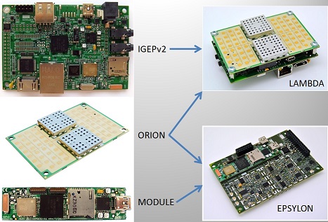
IGEP RADAR SENSOR ORION can be an stand alone radar sensor or it can be plugged with any of 2 different processor boards: IGEPv2 or IGEP COM MODULE.
When combined with IGEPv2 the result is called IGEP RADAR LAMBDA, while when combined with IGEP COM MODULE the result is called IGEP RADAR EPSILON.
The next picture show both combinations:
Identify the different parts of the radar sensor ORION
It is very important you are able to identify the basic parts of the radar in order to avoid wrong set ups of measurement.
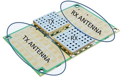
The next picture show which is the 24GHz transmitting antenna, the receiving antenna, the transmitter (TX) and the receiver (RX):
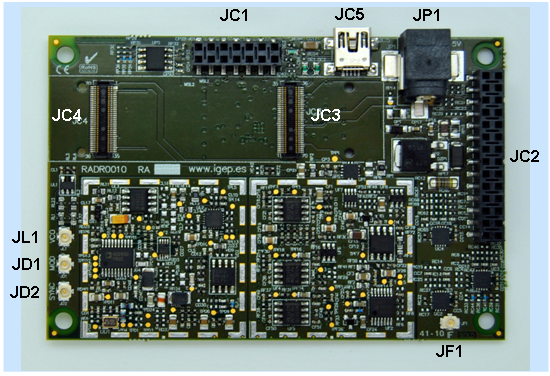
You can also take a look at the bottom face:
JL1 gives you access to the VCO signal
JD1 is the modulation signal
JD2 is the synchronism (you can use this signal to visualise the others on an oscilloscope)
JF1 is the IF signal
JC2 is the expansion connector for IGEPv2
JC4 and JC3 are the expansion connectors for IGEP COM MODULE
JP1 is the power connector
Place the Radar on a stable surface
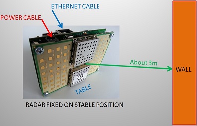
Place the radar over your desk and oriented with the ORION board (antenna) facing a wall of your office with nothing in between in order to have a clearly dominant reflection. A distance of about 3 meters between the radar and the wall would be good to make a first measurement.
Network
You may now plug the Ethernet cable into the 10/100 Ethernet jack of the IGEPv2 board of the radar to get network access. The default firmware configures the Ethernet device with static ip address 192.168.2.189. It is possible to use also 192.168.5.1 or, if you want to be connected to a WiFi network, then you must use 192.168.6.1.
Start your PC and plug the Ethernet cable to it.
Source Power
Now, before you apply the source power to the radar, ensure the equipment is fixed over your desk and the cables do not move the radar. Once the radar is fixed facing to the wall, you can power it through any of its power connectors: J200 on IGEPv2 board or JP1 on ORION board. Remember you can power the radar through any of both connectors but never apply power to both at the same time. Here there is a diagram of an ideal measurement over a wall:
Radar Field of View
Be aware of the radar angle of detection. The radar will only detect objects within its field of view. The angle of detection is about 24º in horizontal direction and about 12º in vertical direction:
Wait few minutes
Once you apply power, please wait a few minutes while IGEPv2 board boots with the default firmware flashed on the internal memory. You will see LEDs from IGPv2 board blinking until system has booted, then you will see a fixed lighted green LED.
Run Web Browser on PC
Run a web browser on your PC with the ability to work with gnuplot4.6. We recommend the use of "Mozzilla FireFox" web browser that you can install and download for free at: http://www.mozilla.org/en-US/
Connect to Radar IP
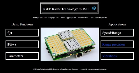
Put the radar IP 192.168.2.189 on the web browser. If the radar has already started you will see the Home page of the web radar application demo, if not, please be patient and wait a little bit more until the radar starts. You will see a home page similar to this one:
Congratulations!
You have successfully connected with radar. Now you can start to make measurements and learn about radar possibilities.
Do not worry if your home page differs from the picture, there are some different format versions but are equivalent in features.
Make your first measurement
To see the time domain IF radar signal in real time, you can click on the icon "f(t)":
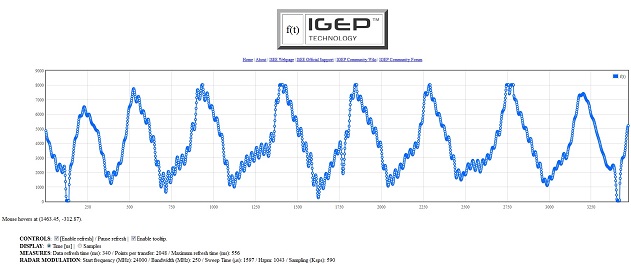
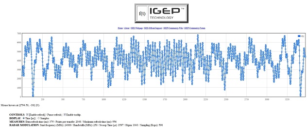
You should see a wave similar to the next picture, this is a dominant sinus.
Be aware the application demo is designed to work on an environment with only a single target scenario so it is very probably you may see quite different signals than the presented here due to multiple reflections in your room, but this is normal, and this is the ability of radar technology to detect multiple objects at the same time, we encourage you to develop your own application and process the IF signal information to detect not only one but several objects. See next guides if you want to learn more about this. To be sure your radar works well, we recommend you find an adequate environment without multiple reflections before to make any wrong conclusions.
What is Time domain signal
The time domain signal window shows the 2048 samples captured of the IF radar signal on each captured frame.
Y axis represents the signal voltage.
X axis represents the time in microseconds or also it can be the sample number.
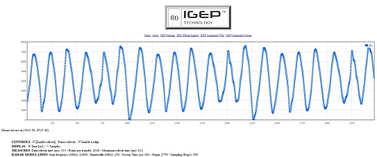
In the picture below we can see a measurement using a -T 600 modulation over a wall about 2m distance from radar. As we will see later, modulation parameters can be changed, in this case we have selected a modulation ramp with a duration of 600us. Considering that the time to get 2048 samples with the default modulation is 3,471ms and we can see about 20 periods of the sinusoidal signal this means that the dominant sinus shown below is about 5,760KHz frequency. The frequency of the IF radar signal is proportional to the distance from the radar to the target (in this case the wall).
We can know at any moment the exactly parameters the radar is working on the below lines of the graphs:
In this case we can identify on the last line the modulation parameters used to make the measurement: The radar start frequency is 24 GHz with a bandwith of 250MHz and a modulation ramp of 604us. Note that although we have selected 600us the radar has a limitation in discrete values and has been configured with the closest value, in this case 604us. We can see also the sampling rate (590ksps) and the modulation parameter Hzpm (herz per meter) that indicates the IF frequency relation with distance.
The "MEASURES" line indicates a refresh time of 333ms (this means that in this moment we visualise about 3 frames per second) and the points per each transfer are 2048.
The "DISPLAY" line offers the possibility to change the units of the x-axis. We can select time or samples.
The "CONTROLS" line let us to activate or de-activate the tooltip (check with the mouse the exactly coordinates of an specific point on the graph) and also generate a data list by deactivating the "Enable refresh" option.
What's This?
Why I am getting this weird signal? It has no sense, my Radar does not works!
No. Please, be patient, this is completely normal, your radar works well. If you are getting a signal like this or even still more strange this means that you are detecting different objects. This signal is the result of adding different sinus waves with different frequencies resulting on an apparently noisy signal but in fact is a typical IF radar signal on a multitarget environment. Our main objective now is try to get a clear signal from a single target to start learning with the radar, so please try to slightly change the radar orientation in order to get only a single reflection, or if you are on a small room, try to go to a better scenario, on a wider room with few objects or simply outside close to a wall.
Basic FMCW Radar Theory
You can check chapter 9 of the user manual to get more in detail about radar theory. Basically, a Radar with continuous wave linear frequency modulation (FMCW) follow the next equation:
hzpm =2*BW/(V*T)
This equation gives the relation between the target distance and its corresponding IF frequency (hzpm) where:
hzpm: "Herz per meter" is the ratio between IF signal frequency (in Herz) and target distance from radar (in meters)
BW: RF output frequency bandwidth in Hz
V: media electromagnetic wave propagation speed (3*108m/s by default).
T: FM linear Modulation sweep time in seconds.
In our example, as the modulation has the next paramenters:
BW=250MHz
T=604us
V=3*108m/s
the resulting hzpm is 2759Hz/m
So, if the measured IF radar signal frequency is 5,760KHz it means the target is at a distance of 2,08m from the radar.
Considering the radar has an offset of about 0,35m (this is due to the microwave signal has this electrical lenght internally on the equipment before to reach the antenna) the real distance results in 1,73m
What is Frequency domain signal
The frequency domain signal is the result of applying the FFT to one ramp modulation interval of the 2048 sampled IF radar signal captured samples.
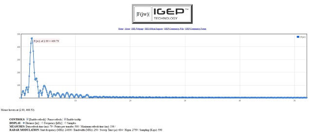
You can see the spectrum of the radar IF signal in real time thanks to the power of the OMAP processor, by clicking on the "F(jw)" icon:
The radar application takes the samples of a single ramp and, if needed, it completes the rest with zeros (padding), thus completing the 2048 samples. Then it performs the FFT over these 2048 samples, resulting on the spectrum of the signal with 2048 points resolution:
Following our example, the above picture shows the FFT of the measurement. Y axis represents signal strenght and X axis represents the FFT sample. Note that only the 500 first samples are shown.
We can see a dominant peak centered about sample number 16. This peak should correspond to the measured dominant sinus of 5,760KHz on time domain graphic.
The sampling rate used by the equipment with the default modulation is 590Ksps. This means that each sample of the FFT represents 590000/2047=288,2Hz.
If the peak is centered about sample 20 it means the frequency represented is 20*288,2Hz=5,764KHz, thus corresponding with accuracy with the calculations made on time domain.
We can see other small peaks. These peaks are due to other reflections on the room at a longer distance. So here an example of the possibilities of the radar to detect several targets at different distances. But by the moment is better if we pay our attention on a single target scenario to keep learning about the radar signal and later we will be able to analyse more complex scenarios.
Compare Measurements
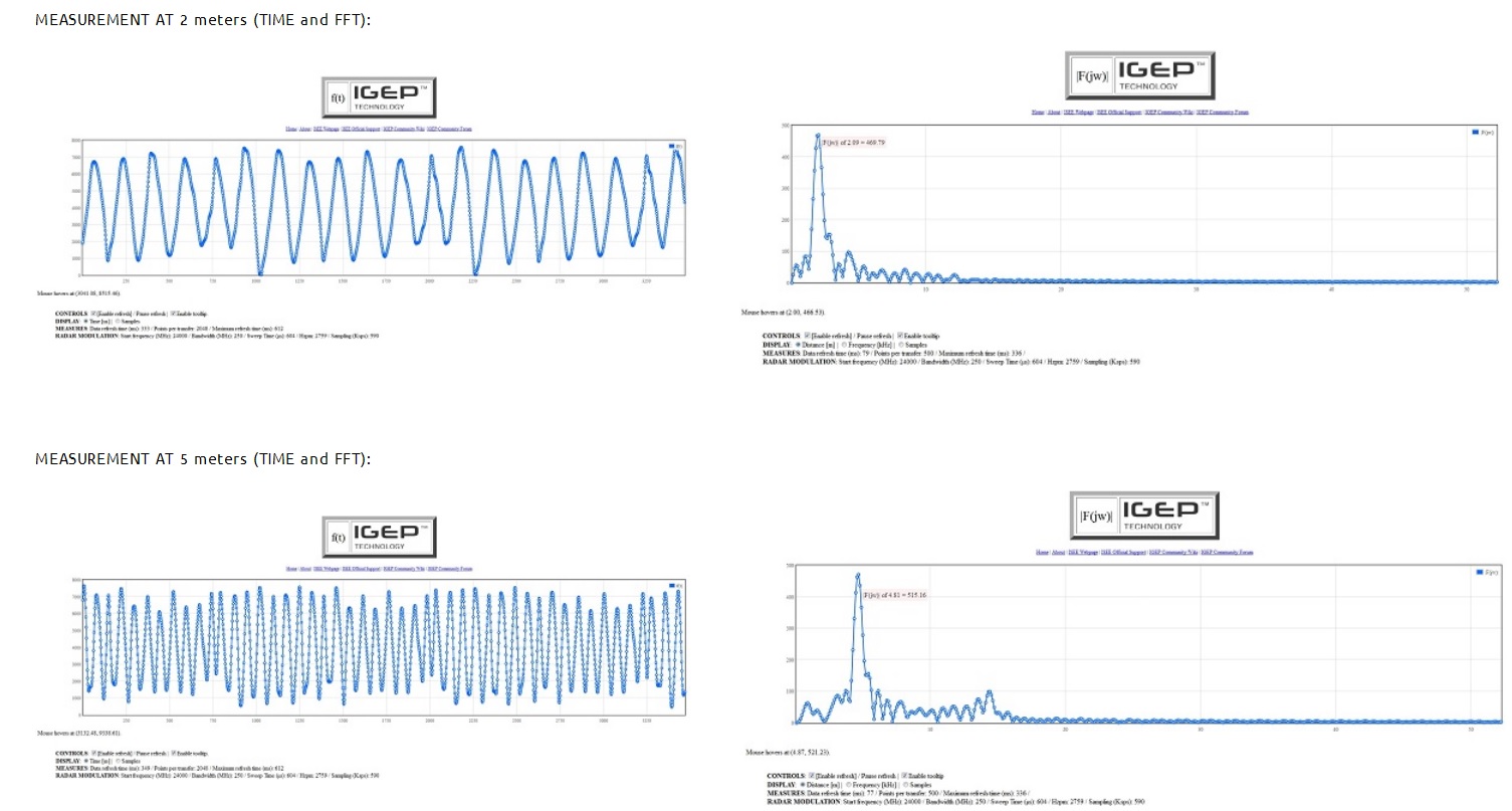
Now you can move the radar and make measurements over the wall at two different distances. For example, make a measurement with the radar at 2m distance and another measurement with the radar at 5m distance. You should get similar results as the following for 2m and 5m in order:
It can be clearly shown how the IF radar signal increases frequency when the target gets more and more distance from the equipment. Look at the increment in periods (frequency) in the time domain signal, and the FFT peak has moved towards higher frequencies.
What is "Speed/Range" section
In the right column of the Home Page we can see three different applications of the radar. Only "Speed/Range" demo application is activated, please if you are interested in the others contact with us at mailto:radar@iseebcn.com
Now you can also make use of "Speed/Range" web application demo feature.This application demo measures the speed and range of a single object and can be used for example for traffic management systems.
Click on "Speed/Range" icon:
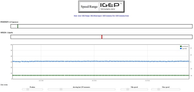
In case of a wall at 6.1m distance you should get something like this:
Note that in this case you get always the same position (6.1meters) and speed (0Km/h) as our target is a no moving object (wall).
You have a real time bar indicating the target range (green) and another real time bar indicating the speed (blue).
There is also a graphic where:
Left Y axis: is the target range in meters.
Right Y axis: is the target speed in Km/h
X axis is time
Each point of the graph is one combined position-speed measurement, position in green color and speed in blue color.
You can see on next chapter examples of real traffic measurements where you can see how the radar track the vehicles measuring its position and distance.
What is "Parameters" section
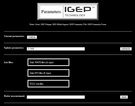
This is the most interesting feature of the web application demo. By clicking on "Parameters" icon you will get access to the heart of the radar:
You will be able to make measurements with the modulation you want, by simply prompting the parameters on the rectangles.
There are three sections:
SECTION-1: CURRENT PARAMETERS
Clicking on "Check" icon you will get the last modulation parameters modified.
SECTION-2: UPDATE PARAMETERS
You can type in this section the modulation parameters you want to change. For example, if you want to reduce the modulation bandwith to 150MHz and increase the sweep time to 5000us you should type: -W 150 -T 5000 and then click on "UPDATE" icon. Then, from now the radar is configured with these new parameters and all measurements will be done in these new conditions until a new parameter change is performed.
SECTION-3: LIST FILES
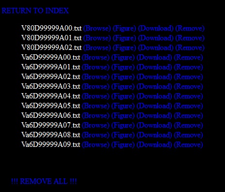
You can check at any moment the data files you have saved on the radar by clicking on any of the three buttons, depending if you only want to check sample files, or FFT files or all the files.For example, if you click on "Only WAVE Files" button it will appear a list of files of the captured data similar to this:
You have the possibility to:
-Browse: represent a time domain graphic of its contents.
-Figure. the same as before
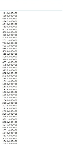
-Download: Check the data contained on this file, this is a column with the 2048 samples of the IF radar signal. You can select and copy to a text file for post-processing
-Remove: click here if you want to remove this file
When clicking at "Download" option you will get a column with all the 2048 captured samples. This is useful to get measurements data and copy to another processing software application like excel or matlab:
SECTION-4: RADAR MEASUREMENT
This feature is interesting if you want to use the web application demo as a console where you can configure the radar with different modulations and get the results prompted on the screen or saved on a text file.
For example, put in this section the next commands:
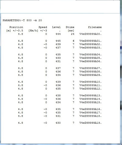
-T 800 -m 20
and click on "RUN" button
-T 800 means you want a modulation with 0,8ms sweep time
-m 20 means that you want to make 20 consecutive measurements
You can check a complete explanation of each parameter on the user manual of the radar.
The result obtained over a wall at 4.8m distance is like this:
The screen shows the result of each of the 20 measurements done on 20 rows, one row per measurement:
1st column shows the measured target position (4.8m)
2nd column shows the measured target speed (in this case 0Km/h as the wall is no moving)
3rd column shows a value proportional to the measured signal strength.
4th column indicates the delta time between each measurement. In this example the radar did each measurement in only 7ms. This time includes the time to program the modulator, perform the ramp modulation, capture the IF radar signal with the ADC, process the data, and show the result.
Finally, the last column indicates the name of the captured file. IMPORTANT: This file will be generated and stored ONLY if you add the parameter -w
-w means that you want to write all the measurements on a file (there will be generated 20 files, one for each measurement, and each one with 2048 samples)
SECTION-5: PARAMETERS
This section is a list of all the parameters that can be used to configure the radar.
{value} means that the parameter has to be followed by a value. [ ] contains the default value.
Check IGEP RADAR LAMBDA user manual if you want to know more about the meanning of the file names.
Managing Files
IGEP RADAR LAMBDA offers several ways to manage its files. Here we present some of the most interesting but of course you can use others if you prefer:
Files with web demo
We have already seen on previous section how to manage files with web demo application. You click on "Parameters" icon, then you go to "List Files" section and select the file you want.
By clicking on "Download" option you obtain a list of 2048 values that represent the captured samples if you have selected "Wave" files or the FFT values if you have selected "FFT" files.
You can use the mouse and select all or only one part of the data, copy and paste to a text file for later processing with other applications like excel, labview or matlab.
You can also click on "Edit" section of your browswer, then click on "Select All", then click on "Copy" and then paste all the data into a text file.
And there is a third option, by clicking on "File" section of your browser and simply "Save as" text file.
Files using WinSCP
You have a second option to manage files by using the WinSCP free application.
Once installed you only have to connect to the radar and start managing files as with other explorer applications.You can edit, copy, paste, remove and rename files on an easy way.
Files using Linux
You have a third option to manage radar files.
You can do it using the console and using the standard Linux commands. Here are some useful links and basic commands:
cd to change directory path
rm to delete a file
mkdir to make a directory
cp to copy a file
Capture measurement results
Linux is an interesting environment to generate files of radar measurement results. Here we present some examples on how to save measurement results into a file:
Example 1:
You want to capture 5 consecutive measurement results into a file named measure5.txt. then you must prompt the next command line:
./radar -m 5 >measure5.txt
NOTE: Remember you must be in the "radar" directory and you must execute "radar_init.sh" at least once before start doing measurements.
Now you can check the measurement results in the generated measure5.txt file, and you will see something like this:
Position Speed Level Dtime filename
[m] +/-0.5 [Km/h] +/-3 . [ms] .
3.9 1 417 27 V70D99999A00.
3.9 1 414 8 V70D99999A01.
3.9 1 422 9 V70D99999A02.
3.9 1 423 9 V70D99999A03.
3.9 1 414 9 V70D99999A04.
Where each row shows the result of each of the 5 consecutive measurements, in this particular case it was measured a fixed target at a 3.9 meters distance from the radar.
NOTE that it only takes about 9ms time to make each measurement.
NOTE also that the file names with the ADC captured data are generated but the files are not saved. They are only saved if you add the command -w
Example 2:
You want to capture 20 consecutive measurement results into a file named measure20.txt. In addition you want to use a modulation sweep time of 1,15ms and you also want to generate a file of the ADC captured data for each measurement. Then, in this case, you must prompt the next command line:
./radar -T 1150 -m 20 -w >measure20.txt
Now you can check the measurement results in the generated measure20.txt file, and you will see something like this:
Position Speed Level Dtime filename
[m] +/-0.5 [Km/h] +/-3 . [ms] .
4.9 -1 866 61 V70D99999A00.
4.9 -1 861 106 V70D99999A01.
4.9 -1 839 97 V70D99999A02.
4.9 -1 846 91 V70D99999A03.
4.9 -1 833 92 V70D99999A04.
4.9 -1 840 141 V70D99999A05.
4.9 -1 864 92 V70D99999A06.
4.9 -1 847 116 V70D99999A07.
4.9 -1 836 92 V70D99999A08.
4.9 -0 816 220 V70D99999A09.
4.9 -1 818 92 V70D99999A10.
4.9 -1 825 139 V70D99999A11.
4.9 -1 820 91 V70D99999A12.
4.9 -1 825 91 V70D99999A13.
4.9 0 800 166 V70D99999A14.
4.9 0 802 90 V70D99999A15.
4.9 0 802 92 V70D99999A16.
4.9 0 807 142 V70D99999A17.
4.9 -0 805 90 V70D99999A18.
4.9 -0 810 110 V70D99999A19.
Each of the 20 rows of the measure20.txt file shows the measurement result in range and speed, in this particular case it was measured a fixed target placed at 4.9 meters distance from the radar.
NOTE that it takes about 100ms time to make each measurement. This is more than previous example due to now the equipment has to write one file after each measurement.
NOTE also that the file names with the ADC captured data are now generated and saved because we have used parameter -w. You should find the 20 generated files in "radar" directory. If you look the contents of one of these files you will see something like this:
6384.000000
6260.000000
6156.000000
6083.000000
6043.000000
6036.000000
6047.000000
6075.000000
6099.000000
6107.000000
6080.000000
6012.000000
5888.000000
5711.000000
5467.000000
5164.000000
4819.000000
4443.000000
4056.000000
3652.000000
3267.000000
2903.000000
2568.000000
2268.000000
2008.000000
1787.000000
1599.000000
1439.000000
1316.000000
1215.000000
1135.000000
1083.000000
1052.000000
1048.000000
1087.000000
...
...
completing the 2048 samples of each measurement capture
The ADC captured files can be used to make your own data processing algorithms.
Example 3:
You want to capture 7 consecutive measurement results into a file named measure7.txt. In addition you also want to use a modulation sweep time of 0,9ms and generate a file of the ADC captured data for each measurement. In order to identify your measurements you want to name these files with 12345. Then, in this case, you must prompt the next command line:
./radar -T 900 -D 12345 -m 7 -w >measure7.txt
Now you can check the measurement results in the generated measure7.txt file. You will see 7 rows with the position and speed measured:
Position Speed Level Dtime filename
[m] +/-0.5 [Km/h] +/-3 . [ms] .
4.9 -1 632 48 V58D12345A00.
4.9 -1 630 92 V58D12345A01.
4.9 -1 629 91 V58D12345A02.
4.9 -0 645 92 V58D12345A03.
4.9 1 619 91 V58D12345A04.
4.9 1 587 149 V58D12345A05.
4.8 -0 611 91 V58D12345A06.
If you look in the "radar" directory you will find the 7 data captured files containing the 2048 samples measured by the ADC on each measurement, and these files include the desired extension name: V58D12345A00.txt, V58D12345A01.txt, etc.
The first three digits of the file name are automatically generated depending on the modulation sweep time. You can check the user manual fore more details.
Next Steps
Congratulations! You have made your first measurements and started to understand how the radar works. You also know most of the features of the radar application demo. Now you are able to do the next steps with the radar and try to adapt it to your specific application.
You can go now to take a view of different radar applications on "What can I do with IGEP RADAR LAMBDA" section or go directly to the "Start developing with IGEP RADAR LAMBDA" section.
Radar Applications: Examples
this section will show you some real measurements and set-ups where IGEP RADAR LAMBDA can be successfuly used
Security
Security is one of the field applications of radar technology. IGEP RADAR LAMBDA has been used for these purposes, we want to show you here some of the results.
Measurements of a person approaching by walking slowly the radar were made during 7 seconds, capturing 1.000 measurement files.
The modulation used was: -T 1600 -m 1000 -w
This modulation means:
-T 1600 ===> program modulator with a 1,6ms modulation sweep time
-m 1000 ===> make 1000 consecutive measurements
-w write ===> and save the captured data into text files
The 1.000 measurement files were captured with the radar and processed later with matlab on a PC.
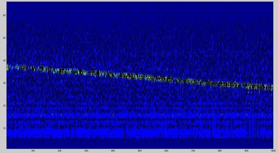
FFT was made for each measurement obtaining the next 2D plot with matlab:
2D plot of 1.000 consecutive frequency domain radar signals detecting a person
Y axis: represents twice the distance
X axis: represents the measurementfile number (so it can be considered as time)
It can be noted that the person is detected from about 18m in the first measurements and is moving towards the radar until 14m distance in the last measurements.
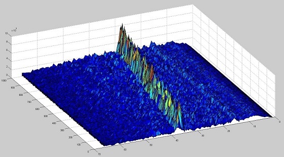
The next is a 3D plot of the same data, where Z axis is the FFT module level:
3D plot of 1.000 consecutive "radar images" of a person
It can be shown that the person can be clearly tracked over the signal noise level (blue color).
20m range can be acceptable in most security systems but it is possible to apply CFAR processing techniques in order to increase the range over 100m. In addition, some more directive antennas could be developed to improve this parameter, and also developing a coherent system. Please contact radar support if you are interested on a development for an specific application.
Traffic
Radar Traffic Control Systems is another interesting field of application for radar.
IGEP RADAR LAMBDA has been used on this kind of applications, we would like to show you some of the measurements performed.
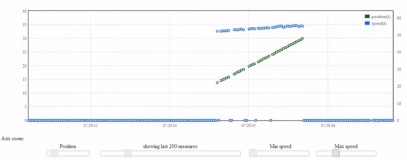
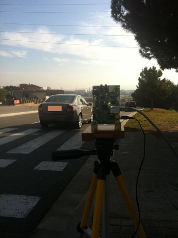
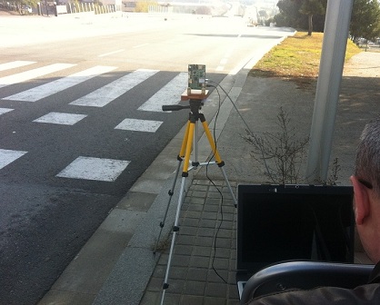
The next picture is a graph obtained making use of "Speed/Range" feature of the web radar application demo. It was obtained placing the radar on on a tripod close to a road on one side, with the radar oriented on a 15 to 30 meters field of view, as shown on below pictures:
It can be clearly seen how radar tracks the target from 13 to 31 meters (linear green points) and how the target is slightly increasing the speed from 54 to 56Kmph.
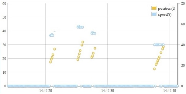
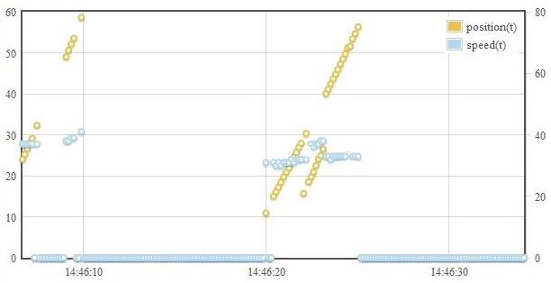
In the next picture several targets were detected in different time intervals:
Real measurements of 4 vehicles tracked in range (orange points) and speed (blue points)
Left Y Axis: Range in meters
Right Y Axis: speed in Km/h
X Axis: Time (hh:mm:ss)
The first vehicle was tracked from 15 to 25m at a speed of 50Km/h
The second vehicle was tracked from 18 to 33m at a speed of 59Km/h
A third vehicle was tracked from 20 to 28m at a speed of 52Km/h
Finally the fourth vehicle was tracked from 12 to 29m at a speed of 40Km/h
The bars indicate the range and speed in real time while the vehicles are being detected and cannot be shown in this picture but the graph reflects the history of the measurements.
Set up used to make the measurements: Radar fixed on a tripod oriented on one side of the road
The modulation used to make this measurement was:
-T 5000 -x 3000 -X 75000 -l 80
-T 5000 sets the modulation sweep time to 5ms
-x 3000 ===> this is a limitation on the processing range, in order to avoid false measurements due to close objects, closer than 3m.
-X 75000 ===> the same as before but applying for far objects, beyond 75m.
-l 80 ===> this is the signal level threshold. If the radar detects a signal over this level it will start making measurements until level returns below this threshold, when the radar will stop taking measurements. Each time it detects a signal over this threshold it will present the results. This parameter is very important in order we obtain only desired signals and not noise that would provide unreadable results.
There is not a fixed rule to obtain this threshold value because it depends on a lot of things, mainly of the modulation applied, the environment and the type of measurement, so the best is to make first some trials to adjust this value on an empirical way until the system works properly in your specific application and you obtain readable results.
You have to put this modulation parameters on the command block of the "Parameters" window and press enter.
Note that each application needs to optimise its own parameters. You can tune the parameters in order to adapt better to your application. For example you may be will get better results if you use a different modulation sweep time, may be -T 6000 is better for your application. Just try and get the best configuration for you, this is one of the purposes of the radar evaluation board.
The next graph is the result to orient the radar to another direction, thus increasing the detection range up to 60m.
Note that an important thing to consider in this kind of measurements is the correct orientation of the radar. This is something you also must empirically optimise for your specific application.
Measurements obtained orienting the radar to get a wider range, up to 60m
Picture of the set up used: radar fixed on a tripod, oriented to de road and laptop to monitor the data in real time
Vibrations
Radar technology can also be used to make non contact remote measurements of building vibrations with high precision level.
This is a very interesting application on the construction area.
IMPORTANT: An special software has been developed to this specific application and cannot be done with IGEP RADAR LAMBDA radar application demo. If you want to use this feature you must contact with radar support and we will study your case and make you an offer for an special software.
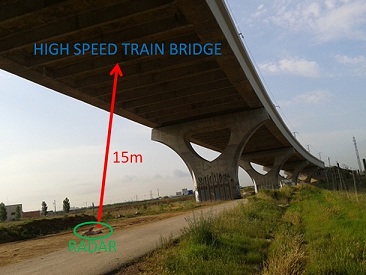
The next picture show the construction that was monitored. It is a 344 m length viaduct, located in Sant Boi, over the Llobregat river. High speed trains pass over this bridge and the purpose of the measurements is to detect the vibration of the construction while trains are passing:
Measurements set up: IGEP RADAR LAMBDA with special software is placed on the ground facing the top of the viaduct at a distance of 15m
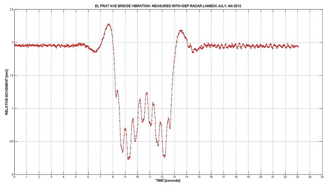
The next figure show the graphic obtained at the time the train was passing over the bridge. This graphic can be shown in real time while train is passing over the bridge. The data can be also captured for further processing. The graphic represents the relative position of the top of the viaduct over the ground. Yes, the structure moves 2mm, will you take the next high speed train? Do not worry, this is normal and you do not have to worry about it, this vibration response has a normal profile.
The advantage of this kind of measurements is that depending on the vibration wave profile engineers can detect structure problems, in the same way a doctor can check if your hearth is OK by lookintg at an EKG.
Vibration wave graph obtained on the measurement. It can be clearly shown the high precision of IGEP RADAR LAMBDA using special data processing
Y Axis: Relative movement between viaduct top and ground in millimeters
X Axis. Time in seconds
We can see from the graph that the radar technology has a precision of up to 50 micrometers
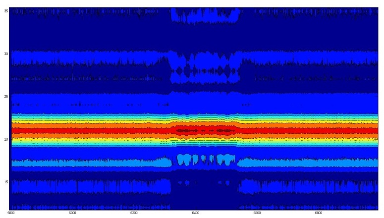
2D graph representing frequency domain measurements.
Y Axis: Represents the sample number of the FFT of the captured data so, it is the Frequency axis
X Axis: represents the Captured file number, so it is the Time axis
This is another way to present the results, by representing all the measurements FFT. This graph was obtained processing the captured data with matlab on a PC, they are not plotted by the radar equipment. It can be seen the peak due to the viaduct top reflection, and in the mid measurements it can be noted the vibration during the time the train is passing.
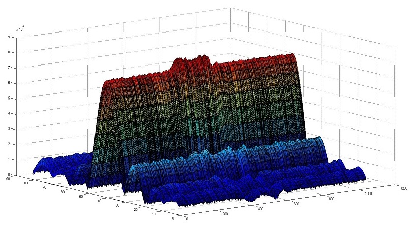
The figure below is a 3D representation of the same: FFT module of all the measurements. Look at the vibration in the central area.
3D graph representing frequency domain measurements.
Tank Level Gauge
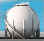
Radar technology can also be used to make non-contact precise tank level measurements.
IGEP RADAR LAMBDA can be used on this kind of application when pressure and temperature conditions are not extreme and no chemical corrosive material is surrounding the equipment. You only have to install the radar at the top of the tank with the antenna facing the material surface contained on the tank and start measuring range.
In case of extreme environmental conditions it would be needed to develop special antenna that can support high pressures and temperatures. ISEE engineering team is able to develop such kind of devices, please contact with radar support if you want we study your personal case.
Horn antenna to be used on extreme environmental conditions
The following applications require the development of an specific hardware and/or software to convert IGEP RADAR LAMBDA into a product. Please do not hesitate to
contact with radar supportif you want we study your personal case:
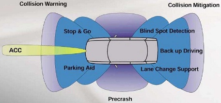
Automotive
Radar technology is beign more and more used on automotive safety systems. IGEP RADAR LAMBDA can be an interesting first step in order to evaluate the feseability of such systems and the reference design for developing more specialised products.
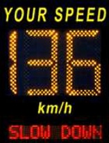
Speed Information Display
IGEP RADAR LAMBDA can be used in combination of a LED Display to develop Speed Information Displays:
UAV Altimeter
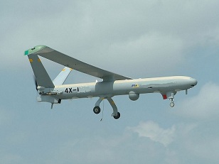
IGEP RADAR LAMBDA can be used as short range altimeter for Unmanned Aerial Vehicles.
The estimated range of detection is from 1 to 100meters so, helping on take off and landing of the UAV thanks to the centimeters precission of K-Band radar technology in comparison with the meters precision of traditional 4GHz altimeters used traditionally on avionics.
Marine Radar
Radar technology is widely used on marine detection systems. Traditional radars use pulsed modulations requiring high RF power levels, affecting power consumption and security of tripulation. FMCW Radar systems are bing more and more used in this application due to its higher precission and its drastically reduced power consumption.
Smart Cities: Intelligent Lighting Systems
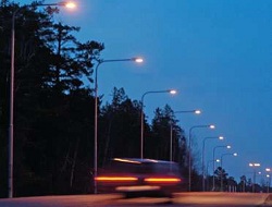
Radar technology can help to develop intelligent systems for cost and energy savings on Smart Cities systems applications. One example is the Intelligent Lighting System consisting on activation of a row of street lights only when the radar detects a person approaching the area, thus saving lot of illuminating hours with nobody in the street. IGEP RADAR LAMBDA could be integrated on this kind of energy efficient systems.
Sports
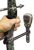
Radar technolgy can be also used in several sports where ball speed or trajectory is an important source of information to improve performance. Archers, Tennis and Golf players are becoming more and more dependants on this kind of information in order to improve their techniques.
Calibration
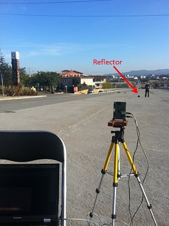
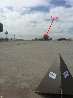
Radar calibration is done with special trihedral reflectors in order to measure its maximum range with precision. The next pictures show real 70m distance that radar is able to detect a 20cm trihedral reflector on a free space environment:


