


User:Albert
Main Page Proposal
|
|
|
|
|
|
IGEP Technology devices features table proposal
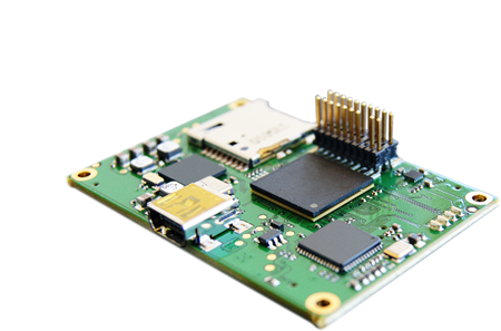
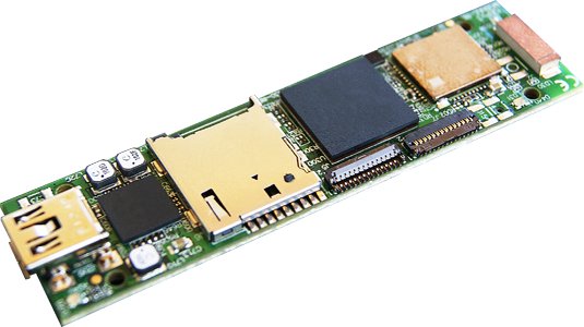
| IGEP0032 | IGEP0030 | IGEP0020 | IGEP0010 | |
| Product name | IGEP COM PROTON | IGEP COM MODULE | IGEPv2 | IGEP0010 |
 |
 |
 |
 | |
| Devices and interfaces | (discontinued product) | |||
| ARM CPU | OMAP3530/DM3730 720MHz/1GHz | OMAP3530/DM3730 720MHz/1GHz | OMAP3530/DM3730 720MHz/1GHz | |
| DSP | TMS320DM-C64+ 500 Mhz / 800 Mhz | TMS320DM-C64+ 500 Mhz / 800 Mhz | TMS320DM-C64+ 500 Mhz / 800 Mhz | |
| RAM Memory | 512 MBytes / 200 Mhz | 512 MBytes / 200 Mhz | 512 MBytes / 200 Mhz | |
| MicroSD Card Reader | x 1 | x 1 | x 1 | x 1 |
| USB 2.0 Host | x 1 | x 1 | ||
| USB 2.0 OTG | x 1 | x 1 | x 1 | x 1 |
| RS232 | x 1 | x 1 | ||
| RS485 | x 1 | x 1 | ||
| JTAG | x 1 | x 1 | x 1 | |
| Stereo audio In/Out | x 1 | |||
| DVI on HDMI | x 1 | |||
| Ethernet | x 1 | x 1 | ||
| Wifi | x 1 | x 1 | ||
| Bluetooth | x 1 | x 1 | ||
| EEPROM | x 1 | |||
| S-Video | T.P. | |||
| Camera Interface | x 1 | x 1 | N.P. | |
| Analog to digital converter | N.P. | |||
| Keyboard matrix | N.P. | |||
| User bicolor leds | x 2 | x 2 | x 2 | |
| TFT Interface | N.P. | |||
| RTC Battery Back Up | N.P. | |||
| Expansion connectors | Power and many functionalities from OMAP3 processor | Power and many functionalities from OMAP3 processor | Power 5V and 1.8V, UART, McBSP, McSPI, I2C, GPIO, RS485 with transceiver, Keyboard | |
| Main pages | (coming soon) |
|
|
(discontinued product) |
| |
| |||
| Getting started guide |
|
| ||
| Hardware manual | |
|
|
- O: Available on board
- N.P.: Not populated THESE DEVICES and/or CONNECTORS ARE AVAILABLE, BUT NOT POPULATED BY DEFAULT
- T.P.: Test points
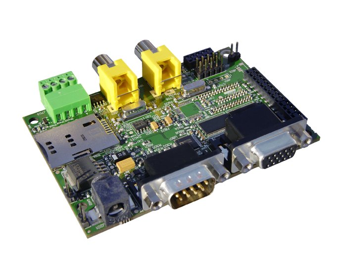
IGEP Expansion Boards
Compatible with IGEP COM MODULE, IGEP COM NEUTRON & IGEP COM PROTON
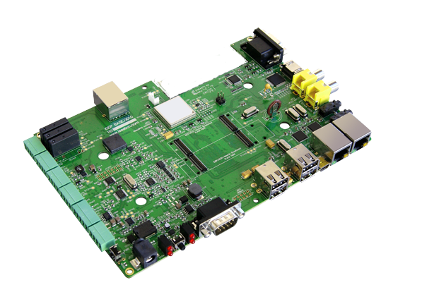
| BASE0010 | ILMS0015 | |||
| Product name | IGEP BERLIN | IGEP PARIS | BASE0010-RA1 | IGEP NEW YORK |
| |
 |
 |
||
| Devices and interfaces | (discontinued product) | |||
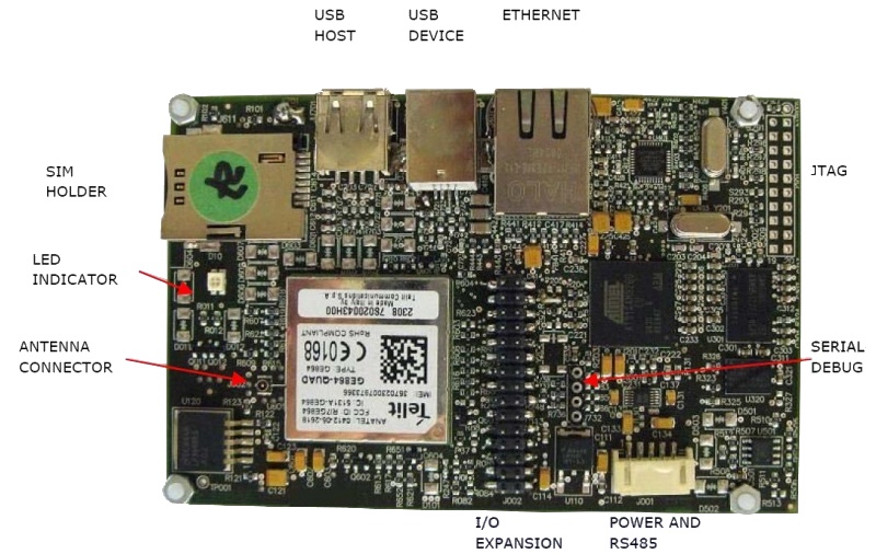
| GSM/GPRS Modem | x 1 | |||
| DVI Video Output on HDMI | x 1 | x 1 | ||
| VGA Video Output | x 1 | |||
| Video Input | x 2 | |||
| Ethernet | x 3 | x 1 | x 2 | |
| USB Host | x 4 | x 1 | x 1 | |
| USB OTG | x 1 | |||
| Stereo audio In/Out | x 1 | x1 | ||
| RS232 | x 1 | x 1 | x 1 | |
| RS485 | x 2 | |||
| CAN interface | x 1 | |||
| Relay outputs | x 3 | |||
| Digital inputs | x 2 | |||
| Analog inputs | x 2 | |||
| Real time clock (RTC) | x 1 | x 1 | ||
| RTC Battery Back Up | x 1 | |||
| Battery charger | N.P. | N.P. | ||
| User leds | x 2 | x 2 | x 1 | |
| TFT Interface | x 1 | x 1 | ||
| Switch | x 2 | x 1 | x 1 | |
| 3 Axis accelerometer | x 1 | |||
| Buzzer | x 1 | x 1 | ||
| EEPROM | x 1 | x 1 | ||
| Expansion connectors | GPIO, SPI, UART, I2C, PWM, DSS | |||
| Main pages | (coming soon) | (coming soon) | |
|
| |
||||
| Getting started guide | |
|||
| Hardware manual |
||||
- x '#': These devices available on board.
- N.P.: These devices and/or connectors are available, but NOT POPULATED by default.
- T.P.: These signals are available via the boards Test points.
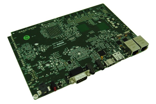
Compatible with IGEPv2
| IGEP0022 | |
| Product name | IGEPv2 EXPANSION |
 | |
| GSM/GPRS Modem | x 1 |
| DVI Video Output on HDMI | x 1 |
| VGA Video Output | x 1 |
| Video Input | x 2 |
| Stereo audio In/Out | x 1 |
| RS232 | x 1 |
| RS485 | x 1 |
| 7" TFT Interface | x 1 |
| 4.3" TFT Interface | x 1 |
| Camera interface | x 1 |
| EEPROM | x 1 |
| CAN Interface | x 1 |
| Main pages | |
| | |
| Getting started guide | |
| Hardware manual | |
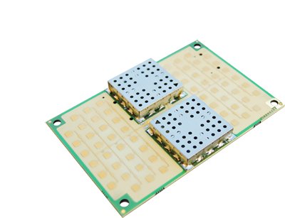
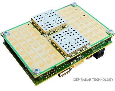
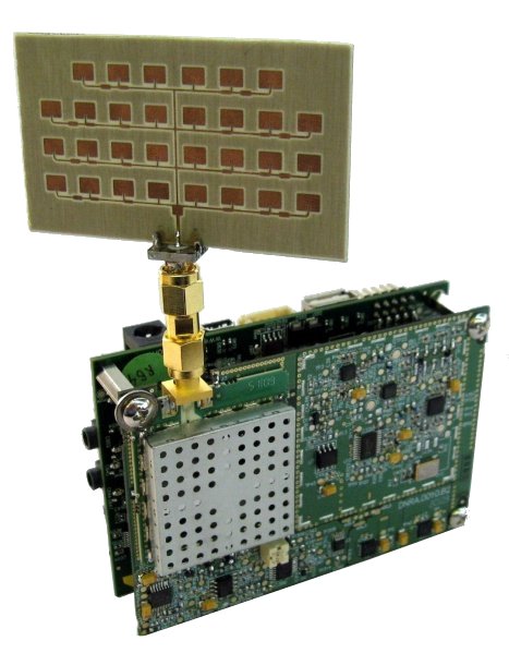
IGEP Radar
| |
RADR0010 |
RADR0000 | |
| Product name | IGEP RADAR SENSOR ORION | IGEP RADAR LAMBDA | IGEP RADAR KIT v1 |
| |
 |
 |
 |
| Main pages |
|
|
|
| |
|
| |
| Hardware manual |
|
|
|
Proposal for new getting started with IGEP0020 board
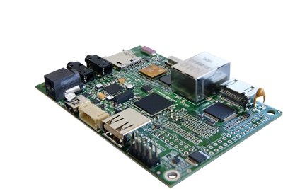
IGEP0020 |

Overview
This page is a starting point for all products of the IGEP0020 family such IGEPv2 Board.
This guide is divided in three different parts:
- Getting started: A basic tutorial about how to connect and boot your IGEP0020
- What can I do?: An extensive article to setup the main peripherals of IGEP0020
- Start developing: Once you have successfully followed the previous tutorials, you are ready to start developing with IGEP Technology. Here you will find some basic tips tricks about how to start with it.
At the right corner of this pages you will find a navigation box with this links.
Getting started
This getting started guide describes how to boot IGEP020 and also gives some basic instructions about how to connect some peripherals.
For further information about this board, there exist other sections where you can find specific and extended contents, in-depth description, valuables web links, etc.
If that is your case, visit the main page of IGEP0020 or check the categories at the IGEP Community Wiki.
Preinstalled software
By default, all brand new IGEP Processor Boards have a firmware installed on its flash memory.
That means that if you power up your board it will run a Linux distribution provided and installed by ISEE.
This distribution consists on a minimal Linux-based distribution with a lite X Window System and GNOME Mobile based applications created with Poky Platform Builder.
Linux distributions
In this tutorial, we are going to use the pre-installed software in your IGEP0020, that is the Poky Linux. But if you wish, you can always update with a new or a different distribution. Check out the Software distributions category.
(explain the main structure of the Linux Kernel and some basic software)
Setting up
First of all, you can begin to add peripherals.
In this tutorial we are going to learn how to connect and the main usage of:
- the serial cable
- a monitor
- a USB keyboard and a mouse
- a network cable.
Do NOT power up your board yet.
Monitor
IGEP0020 has a DVI-D interface where you can connect a HDMI connector to a monitor.
The Digital Visual Interface (DVI) is a video standard interface designed to provide very high visual quality on digital display devices such as flat panel LCD computer displays and digital projectors. It is partially compatible with the High-Definition Multimedia Interface (HDMI) standard in digital mode (DVI-D), and VGA in analog mode (DVI-A).
You will need a cable with male DVI-D connector for the monitor, and male HDMI connector from IGEP0020.
Note that your monitor should be able to support 1024 x 768 @ 60 Hz, which is the default resolution in the preinstalled software.
Serial
In the preinstalled software, the serial port is configured as a Debug interface. That means that if you connect an external device to the serial port you will be able to see the Linux Kernel traces, as the system boots.
(place image of system traces)
Furthermore, you will be able to access IGEP0020 with a termninal client in your host device (a PC with Linux, Windows, etc.)
In this tutorial, we are going to test this feature by connecting an AT/Everex Cable to the 10-pin serial header on IGEP0020 and a null modem DB9 male-male serial cable between the board and your host machine (for example, a PC with Linux, Windows, etc.).
To communicate with IGEP0020 via Serial port you have to connect your host machine to the serial debug port in your IGEP0020.
If you don't know how to do it, refer to the following article: How to setup the IDC10 cable.
If you do not have Serial port in your host machine you might need a USB to Serial converter to test this port.
Once you have set the cable, then you have to run a serial console, or any program that can interact with the serial port in your host machine, such Minicom, PuTTy, Terminal (Windows), etc.
Here is an extended article about how to communicate via serial port to your board: Using serial debug port to communicate.
Audio IN/OUT
External Audio input devices, such as a powered microphone or the audio output of a PC or MP3 player, can be connected to the via a 3.5mm jack (Audio IN).
An external Audio output device, such as external stereo powered speakers, can be connected to the BASE0010 via a 3.5mm jack (Audio OUT).
Keyboard/Mouse
In IGEP0020 you might need a powered hub to connect to most USB.
Connect the USB hub to the USB host connector in your IGEP0020, and then plug your keyboard and mouse into the USB hub.
Only USB 2.0 devices will work in IGEP0020, so if connect any USB mouse 1.0 into the USB host connector without using a USB hub 2.0, it will not work.
Network
IGEP0020 comes with one 10/100BASE-TX Ethernet ports. Plug an Ethernet cable between IGEP0020 and your host machine (or any other network device with ethernet connectivity).
Power up
Once you have connected the peripherals you can apply power to your IGEP0020 (5V DCC).
If you have connected the serial debug port, you will see the system prompts as the board is starting up. Finally you will see the boot prompt asking for login.
You will also see a few LED's flash in IGEP0020 during the system boot(the sequence will be different based on software version).
Finally, if you connected the DVI-D signal (with HDMI connector) to a monitor, the desktop of the preinstalled software will appear on the screen and you will be able to use the mouse and the keyboard, if connected.


The next step is: What can I do with IGEP0020
Important note - Please read these documents before continuing with this article:
- Official IGEP0020 Hardware Reference Manual from ISEE

|
It is highly recommended to update your pre-installed software image to a recent release to ensure you have the latest features and bug fixes. |
|---|