Difference between revisions of "RADR0010 Features"
From IGEP - ISEE Wiki
| Line 4: | Line 4: | ||
[[Image:Radarv2.jpg|424x269px|Radar v2]]<br> | [[Image:Radarv2.jpg|424x269px|Radar v2]]<br> | ||
| − | |||
| − | |||
| − | |||
| − | |||
| − | |||
| − | |||
| − | |||
| − | |||
| − | |||
| − | |||
| − | |||
| − | |||
| − | |||
| − | |||
| − | |||
| − | |||
| − | |||
| − | |||
| − | |||
| − | |||
= Radar v2 Board Main Specifications<br> = | = Radar v2 Board Main Specifications<br> = | ||
Revision as of 18:23, 28 July 2011
Contents
Radar v2 Board
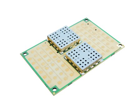
Radar v2 BOARD is a Single Board K-Band Radar Sensor Technology Demonstrator. Designed for using World-Wide 24GHz ISM Band.
This board can be connected to several processor boards for Control and Signal Processing.
Complete Option is compatible with IGEPv2 Board, IGEP MODULE, BEAGLEBOARD and GUMSTIX OVERO.
Radar v2 Board Main Specifications
- K-Band VCO Radar Transceiver
- CW / FSK / FMCW Modes
- ISEE Propietary Microwave Hardware Design
- 24GHz Low Noise Amplifier
- IF Preamplifier
- Bandwidth Limited for low noise performance
- Integrated micro-strip antennas
- Small Profile
- Temperature Range: -40 to +80º C
- Complete Option makes possible Processor Board connection (for Advanced Applications):
IGEPv2,IGEP MODULE, BEAGLEBOARD and GUMSTIX OVERO COMPATIBLE
Radar v2 Standalone Features
- 23GHz to 24,5GHz Operational
- 24GHz to 24,250GHz Specified (24GHz ISM Band)
- +20dBm E.I.R.P.
- Voltage Tuning Range: +1 to +6Volts
- +5V Power
- 2,5W Consumption (Continuous Operation)
- IF Pre-Amplification: 25dB
- IF BandWidth limited 1-32KHz for noise reduction
- Selectable 100Hz to 32KHz Filter for Doppler CW Measurements
- CW / FSK / FMCW Modes
- Single Basic Control Connector:
- Power +5V
- GND
- Vt (VCO Tuning Voltage)
- IF Signal
- 5VCTL2 control port to switch standard or Doppler filtering
- 5VPULSE control signal for pulsed mode operation
- Power +5V
- Released on April 2011.
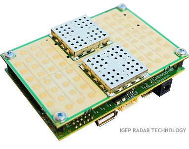
Radar Kit v2 Features ( Radar Kit v2 + IGEPv2 Board )
- K-Band VCO Radar Transceiver
- CW / FSK / FMCW Modes
- ISEE Propietary Microwave Hardware Design
- 24GHz Low Noise Amplifier
- IF Preamplifier
- Bandwidth Limited for low noise performance
- Integrated micro-strip antennas
- Small Profile
- Temperature Range: -40 to +80º C
- IGEPv2 Processor Board for Advanced Applications
- Ethernet Link
- Web Server for Radar Control Configuration and Signal Monitorng in Pseudo-Real Time
- Internet access to Radar: control and monitoring
- High Speed Processing Capabilities if TI OMAP35x DSP is used (FFT, Digital Filtering, etc)
RADAR KIT: Radar v2 Board + IGEPv2 Board Complete Features
- 23GHz to 24,5GHz Operational
- 24GHz to 24,250GHz Specified 24GHz ISM Band)
- +20dBm E.I.R.P.
- Voltage Tuning Range: +1 to +6Volts
- +5V Power
- 3Watt Consumption (Continuous Operation)
- IF Amplification: 55dB
- IF Automatic Gain Control 40dB Dynamic Range
- IF Standard BandWidth limited 1-32KHz for noise reduction
- Selectable 100Hz to 32KHz IF Filter for Doppler CW Measurements
- Selectable 4KHz to 25KHz IF Filter for Narrow Band Precise Measurements
- CW / FSK / FMCW Modes
- Direct Digital Synthesizer Modulator Programmable via SPI Link
- 2 Analog to Digital Converters 1 and 3 MSPS [Optional, only one operational]
- ADC Data Capture via SPI Link
- Basic Control Connector:
- Power +5V
- GND
- Vt (VCO Tuning Voltage)
- IF Signal
- CTL1 control port to switch standard or Narrow Band Pass Filtering
- CTL2 control port to switch standard or Doppler filtering
- PULSE control signal for pulsed mode operation
- Power +5V
- Expansion Connector for IGEPv2 or BEAGLEBOARD:
- Power +5V
- GND
- DDS MODULATOR Programming through SPI Link
- ADC Sampling and Data Capture through SPI Link
- IF Signal
- CTL1 control port to switch standard or Narrow Band Pass Filtering
- CTL2 control port to switch standard or Doppler filtering
- CTL control port for initial sweep and capture data
- PULSE control signal for pulsed mode operation
- Power +5V
- Expansion Connectors for IGEP MODULE or GUMSTIX OVERO Board:
- Power +4.2V
- GND
- DDS MODULATOR Programming through SPI Link
- ADC Sampling and Data Capture through SPI Link
- IF Signal
- CTL1 control port to switch standard or Narrow Band Pass Filtering
- CTL2 control port to switch standard or Doppler filtering
- CTL control port for initial sweep and capture data
- PULSE control signal for pulsed mode operation
- Power +4.2V
- USB-OTG Connector. Operational only when IGEP MODULE or GUMSTIX OVERO is used.
- Power +5V Connector
- EEPROM Programmable via I2C link
- Optional Linear Regulator to extend Input Source Power to +16Volts
- Released on April 2011.


