


Difference between revisions of "Getting started with IGEPv2 EXPANSION"
From IGEP - ISEE Wiki
m |
m |
||
| Line 1: | Line 1: | ||
__NOTOC__ | __NOTOC__ | ||
| − | {| | + | {{Table/IGEP Technology Devices |
| − | | | + | |Tech_Family={{#lst:Template:Links|IGEPv2_EXPANSION_Tech_Family}} |
| − | | | + | |Tech_ID={{#lst:Template:Links|IGEPv2_EXPANSION_Tech_ID}} |
| − | |||
| − | |||
| − | |} | ||
| − | |||
| − | |||
| − | |||
|Name={{#lst:Template:Links|IGEPv2_EXPANSION_Name}} | |Name={{#lst:Template:Links|IGEPv2_EXPANSION_Name}} | ||
|Image={{#lst:Template:Links|IGEPv2_EXPANSION_Image}} | |Image={{#lst:Template:Links|IGEPv2_EXPANSION_Image}} | ||
|ISEE_MainPage={{#lst:Template:Links|IGEPv2_EXPANSION_ISEE_MainPage}} | |ISEE_MainPage={{#lst:Template:Links|IGEPv2_EXPANSION_ISEE_MainPage}} | ||
|ISEE_Hardware={{#lst:Template:Links|IGEPv2_EXPANSION_ISEE_Hardware}} | |ISEE_Hardware={{#lst:Template:Links|IGEPv2_EXPANSION_ISEE_Hardware}} | ||
| − | |||
| − | |||
| − | |||
}} | }} | ||
| − | + | {{Message/Work in progress}} | |
| − | |||
| − | |||
| − | |||
| − | |||
| − | |||
| − | |||
| − | |||
| − | |||
| − | |||
| − | |||
| − | {{Message/ | ||
| Line 137: | Line 117: | ||
[[Category:IGEP Technology Devices Guides]] | [[Category:IGEP Technology Devices Guides]] | ||
| − | |||
Revision as of 18:37, 1 August 2012
|
|
| |
This is a work in progress article. Help other developers like you in the IGEP Community by improving it! |
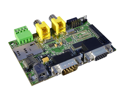
Mounting IGEPv2 EXPANSION
The IGEPv2 EXPANSION connects to IGEPv2 via 5 connectors of 10, 22, 28 and 30 pins located on both boards. First align the biggest 28 pin-connector gently press it until the other connectors insert into their corresponding connectors from the other board.


Adding peripherals
You can begin to add peripherals like Serial port, VGA monitor, CAN bus, a SIM card reader, TFT and Touchscreen and the S-Video connectors.
Jumpers configuration
Some IGEPv2 EXPANSION may include three jumpers that correspond to:
| Jumper name |
Position on board |
|---|---|
|
Telit GE865 GSM/GPRS Modem:
|
 |
|
MCP2515 CAN BUS:
|
 |
These jumpers are designed for test and lab purposes to force a specific device by hardware.
For a normal use of IGEPv2 EXPANSION THESE JUMPERS SHOULD BE REMOVED from the board.
Serial port
Connect a null modem DB9 male-male serial cable between the board and your host machine, use the serial debug port to communicate with the host machine: Using serial debug port to communicate
VGA monitor
Connect a VGA monitor to IGEPv2 EXPANSION VGA connector.
CAN bus
Connect any CAN bus device or network to the CAN bus connector of the IGEPv2 EXPANSION.
SIM card reader
A SIM card reader is provided with IGEPv2 EXPANSION. You may connect a SIM card to use the GSM/GPRS modem to make phone calls or to send SMS or to write and read data from it, etc.
GSM/GPRS antenna
Connect an external GSM/GPRS antenna to the J404 GSC connector.

TFT and Touchscreen
IGEPv2 EXPANSION integrates a LCD backlight driver (Texas instruments TPS61081) and touch screen controller (Texas instruments TSC2046), 4-wire touch screen controller which supports a low-voltage I/O interface which can be directly connected to a SEIKO 7” LCD or to a POWERTIP 4.3” LCD. Use J301 connector for POWERTRIP 4.3" or use J302, J303 and J304 connector for SEIKO 7".

Composite video
There are two composite video inputs via RCA connectors in IGEPv2 EXPANSION.