


Difference between revisions of "Getting started with IGEPv2 EXPANSION"
From IGEP - ISEE Wiki
m (→Connect IGEPv2 Expansion with IGEPv2 Board) |
|||
| (10 intermediate revisions by 3 users not shown) | |||
| Line 6: | Line 6: | ||
|ISEE_MainPage={{#lst:Template:Links|IGEPv2_EXPANSION_ISEE_MainPage}} | |ISEE_MainPage={{#lst:Template:Links|IGEPv2_EXPANSION_ISEE_MainPage}} | ||
|ISEE_Hardware={{#lst:Template:Links|IGEPv2_EXPANSION_ISEE_Hardware}} | |ISEE_Hardware={{#lst:Template:Links|IGEPv2_EXPANSION_ISEE_Hardware}} | ||
| − | }} | + | }} |
| − | |||
| − | |||
| − | |||
| − | |||
| − | |||
| − | |||
| − | |||
| − | |||
| − | |||
| − | |||
| − | |||
| − | |||
| − | |||
| − | |||
| − | |||
| − | |||
| − | |||
| − | |||
| − | |||
| − | |||
| − | |||
| − | |||
| − | |||
| − | |||
| − | |||
| − | |||
| − | |||
| − | |||
| − | |||
| − | |||
| − | |||
| − | |||
| − | |||
| − | |||
| − | |||
| − | |||
| − | |||
| − | |||
| − | |||
| − | |||
| − | |||
| − | |||
| − | |||
| − | |||
| − | |||
| − | |||
| − | |||
| − | |||
| − | |||
| − | |||
| − | |||
| − | |||
| − | |||
| − | |||
| − | |||
| − | |||
| − | |||
| − | IGEPv2 Expansion | + | =Overview= |
| + | This is the 1/3 chapter of IGEPv2 Expansion Tutorial Guide. | ||
| − | + | In this first chapter, we will learn how to connect some expansion peripherals. | |
| − | |||
| − | + | __TOC__ | |
| − | |||
| − | |||
| − | + | =Requirements= | |
| + | In this tutorial we are going to use the following peripherals: | ||
| − | + | * IGEPv2 with its power supply | |
| + | * IGEPv2 Expansion | ||
| + | * Monitor compatible with DVI-D or VGA | ||
| + | * HDMI/DVI-D cable or VGA cable | ||
| + | * TFT touch screen (Powertrip 4.3" or Seiko 7") | ||
| + | * Composite video cable, composite video output peripheral (PAL or NTSC) | ||
| + | * Network cable | ||
| + | * SIM card with an antenna | ||
| + | * DB9 connector | ||
| + | * PC | ||
| − | + | =Getting started= | |
| + | ==Connect IGEPv2 Expansion with IGEPv2 Board== | ||
| + | The IGEPv2 Expansion connects to the IGEPv2 Board through J990, JA41, JA42, JC30 and J960 connectors. Some IGEPv2 Expansion may include three jumpers, you should remove it because they are designed for test and lab purposes. Just take a look on the figure below to mount it: | ||
| − | {| cellspacing="1" cellpadding="1" | + | {| width="200" cellspacing="1" cellpadding="1" border="1" align="center" |
|- | |- | ||
| − | | | + | ||[[Image:Igepv2expconnectoigepv2.PNG|268px]] |
| − | + | ||[[Image:Igepv2expconnectoigepv2 2.PNG|268px]] | |
| − | |||
| − | |||
| − | |||
| − | | | ||
| − | |||
| − | | | ||
| − | | | ||
| − | | | ||
| − | |||
| − | |||
| − | |||
| − | |||
| − | |||
| − | |||
| − | |||
| − | |||
| − | | | ||
|} | |} | ||
| − | == | + | ==Enable IGEPv2 Expansion support== |
| + | IGEP Yocto Firmware comes with IGEPv2 Expansion support. However open igep.ini, you can do this [[How_do_I_edit_my_kernel_command_line | checking following kernel cmdline parameter]]: | ||
| − | + | <pre>buddy=igep0022</pre> | |
| − | + | ==Remote connection via Ethernet== | |
| − | | | + | {{Message/Information Message|title=|message=If you aren't using a Linux operating system, use [http://labs.isee.biz/index.php/IGEP_SDK_Virtual_Machine IGEP SDK Virtual Machine] to connect to the board}} |
| − | | [ | ||
| − | |||
| − | |||
| − | |||
| − | |||
| − | |||
| − | + | In your Host Machine, open a terminal sessions set up an Ethernet alias for your network interface, | |
| − | + | $ sudo ifconfig eth0:0 192.168.5.10 | |
| − | + | connect to the board using the SSH protocol | |
| − | + | $ ssh root@192.168.5.1 | |
| − | |||
| − | + | an empty password for root user should work to access to the shell prompt. | |
| − | + | {{Navigation/IGEP Technology Guides/Getting Started/Ending | |
| − | |||
| − | |||
| − | |||
| − | |||
| − | |||
| − | |||
| − | |||
| − | |||
| − | |||
| − | |||
|Next_Step={{#lst:Template:Links|IGEPv2_EXPANSION_Community_Guides_2}} | |Next_Step={{#lst:Template:Links|IGEPv2_EXPANSION_Community_Guides_2}} | ||
| − | |||
| − | |||
| − | |||
| − | |||
| − | |||
| − | |||
| − | |||
| − | |||
| − | |||
}} | }} | ||
| + | [[Category:IGEP Technology Devices Guides]] | ||
Latest revision as of 10:59, 10 April 2018
|
|
Overview
This is the 1/3 chapter of IGEPv2 Expansion Tutorial Guide.
In this first chapter, we will learn how to connect some expansion peripherals.
Contents
Requirements
In this tutorial we are going to use the following peripherals:
- IGEPv2 with its power supply
- IGEPv2 Expansion
- Monitor compatible with DVI-D or VGA
- HDMI/DVI-D cable or VGA cable
- TFT touch screen (Powertrip 4.3" or Seiko 7")
- Composite video cable, composite video output peripheral (PAL or NTSC)
- Network cable
- SIM card with an antenna
- DB9 connector
- PC
Getting started
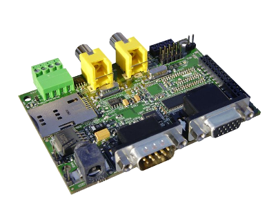
Connect IGEPv2 Expansion with IGEPv2 Board
The IGEPv2 Expansion connects to the IGEPv2 Board through J990, JA41, JA42, JC30 and J960 connectors. Some IGEPv2 Expansion may include three jumpers, you should remove it because they are designed for test and lab purposes. Just take a look on the figure below to mount it:

|

|
Enable IGEPv2 Expansion support
IGEP Yocto Firmware comes with IGEPv2 Expansion support. However open igep.ini, you can do this checking following kernel cmdline parameter:
buddy=igep0022
Remote connection via Ethernet

|
If you aren't using a Linux operating system, use IGEP SDK Virtual Machine to connect to the board |
In your Host Machine, open a terminal sessions set up an Ethernet alias for your network interface,
$ sudo ifconfig eth0:0 192.168.5.10
connect to the board using the SSH protocol
$ ssh root@192.168.5.1
an empty password for root user should work to access to the shell prompt.
You have successfully completed this chapter of the guide.
|

|
If you have any question, don't ask to ask at the IGEP Community Forum or the IGEP Community Chat | 
|