

Difference between revisions of "Getting started with IGEP SMARC EXPANSION"
From IGEP - ISEE Wiki
(→Overview) |
(→Overview) |
||
| Line 27: | Line 27: | ||
{| cellspacing="1" cellpadding="1" width="150" border="1" align="center" | {| cellspacing="1" cellpadding="1" width="150" border="1" align="center" | ||
|- | |- | ||
| − | | [[Image:SERIAL_CABLE_BASE0040. | + | | [[Image:SERIAL_CABLE_BASE0040.jpg|600px]]<br> |
|} | |} | ||
<br> | <br> | ||
Revision as of 11:40, 21 March 2017
|
|
Contents
Overview
This is the 1/3 chapter of the Getting Started with IGEP SMARC EXPANSION Tutorial Guide. In this first chapter, we will learn:
- Connect some peripherals, including monitor and USB peripherals.
- Boot the board.
Upon completion, you will be ready to continue with chapter 2/3 that explains more advanced tasks.
Remote connection via Serial interface
Overview
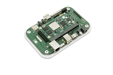
Serial header (J801) lets you debug system with an USB to 3V3 TTL level serial like TTL-232R-3V3 converter from FTDI or compatible reference. The TTL-232R-3V3 converter has 6 pins and IGEP SMARC EXPANSION add a 7th way (3v3 power). The next image shows how to connect it:
 |
Setting up connection
Open the serial on your PC using your preferred serial communications program (minicom) and configure the port as follows:
- 115200
- 8N1
- no flow control (either software or hardware)
Open the serial port and the debug shell prompt should appear.
A detailed guide on how to connect via serial debug port can be found by following this link: Using serial debug port to communicate