


Difference between revisions of "Getting started with IGEP RADAR SENSOR ORION"
From IGEP - ISEE Wiki
m |
|||
| Line 1: | Line 1: | ||
| − | + | {{Table/IGEP Technology Devices | |
| − | + | |Tech_Family={{#lst:Template:Links|IGEP_RADAR_SENSOR_ORION_Tech_Family}} | |
| − | + | |Tech_ID={{#lst:Template:Links|IGEP_RADAR_SENSOR_ORION_Tech_ID}} | |
| − | | | ||
| − | | | ||
| − | |||
| − | |||
| − | |} | ||
| − | |||
| − | |||
| − | |||
|Name={{#lst:Template:Links|IGEP_RADAR_SENSOR_ORION_Name}} | |Name={{#lst:Template:Links|IGEP_RADAR_SENSOR_ORION_Name}} | ||
|Image={{#lst:Template:Links|IGEP_RADAR_SENSOR_ORION_Image}} | |Image={{#lst:Template:Links|IGEP_RADAR_SENSOR_ORION_Image}} | ||
|ISEE_MainPage={{#lst:Template:Links|IGEP_RADAR_SENSOR_ORION_ISEE_MainPage}} | |ISEE_MainPage={{#lst:Template:Links|IGEP_RADAR_SENSOR_ORION_ISEE_MainPage}} | ||
|ISEE_Hardware={{#lst:Template:Links|IGEP_RADAR_SENSOR_ORION_ISEE_Hardware}} | |ISEE_Hardware={{#lst:Template:Links|IGEP_RADAR_SENSOR_ORION_ISEE_Hardware}} | ||
| − | |||
| − | |||
| − | |||
}} | }} | ||
| − | |||
| − | |||
| − | |||
| − | |||
| − | |||
| − | |||
| − | |||
| − | |||
| − | |||
| − | |||
| − | |||
| − | |||
| − | |||
| − | |||
== Identify the different parts of the radar sensor ORION == | == Identify the different parts of the radar sensor ORION == | ||
| Line 40: | Line 15: | ||
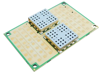
The next picture show which is the 24GHz transmitting antenna, the receiving antenna, the transmitter (TX) and the receiver (RX): | The next picture show which is the 24GHz transmitting antenna, the receiving antenna, the transmitter (TX) and the receiver (RX): | ||
| − | + | [[Image:ORION DETAILS TOPs.jpg]]<br> | |
You can also take a look at the bottom face:<br> | You can also take a look at the bottom face:<br> | ||
| Line 46: | Line 21: | ||
<br> | <br> | ||
| − | + | [[Image:ORION BOTTOM.png]] | |
JL1 gives you access to the VCO signal | JL1 gives you access to the VCO signal | ||
| Line 841: | Line 816: | ||
| − | {{Navigation/IGEP Technology | + | |
| − | + | ||
| − | + | {{Navigation/IGEP Technology Guides/Getting Started/Ending | |
|Next_Step={{#lst:Template:Links|IGEP_RADAR_SENSOR_ORION_Community_Guides_2}} | |Next_Step={{#lst:Template:Links|IGEP_RADAR_SENSOR_ORION_Community_Guides_2}} | ||
}} | }} | ||
[[Category:IGEP Technology Devices Guides]] | [[Category:IGEP Technology Devices Guides]] | ||
Revision as of 12:53, 26 July 2013
|
|
Contents
Identify the different parts of the radar sensor ORION
It is very important you are able to identify the basic parts of the radar in order to avoid wrong set ups of measurement.
The next picture show which is the 24GHz transmitting antenna, the receiving antenna, the transmitter (TX) and the receiver (RX):

You can also take a look at the bottom face:

JL1 gives you access to the VCO signal
JD1 is the modulation signal
JD2 is the synchronism (you can use this signal to visualise the others on an oscilloscope)
JF1 is the IF signal
JC2 is the expansion connector for IGEPv2
JC4 and JC3 are the expansion connectors for IGEP COM MODULE
JP1 is the power connector
Expansion connector
Expansion connector JC1 is intended for control and monitoring of internal radar sensor ORION signals.
JC1 pin-out

NOMENCLATURE
Function names marked with gray shading denote that are available only on demand
<span lang="EN-US" style="font-size:11.0pt;line-height: 115%;font-family:"Calibri","sans-serif";mso-fareast-font-family:Calibri; mso-bidi-font-family:"Times New Roman";mso-ansi-language:EN-US;mso-fareast-language: EN-US;mso-bidi-language:AR-SA" />
<span lang="EN-US" style="font-size:11.0pt;line-height: 115%;font-family:"Calibri","sans-serif";mso-fareast-font-family:Calibri; mso-bidi-font-family:"Times New Roman";mso-ansi-language:EN-US;mso-fareast-language: EN-US;mso-bidi-language:AR-SA" />
· PIN: PIN NUMBER OF THE CONNECTOR. SUBINDEX MEANING:
o PW: Power Line
o DIG: CMOS DIGITAL SIGNAL PORT 1V8 LOGIC LEVELS
o DIG3: CMOS DIGITAL SIGNAL PORT 3V3 LOGIC LEVELS
o DIG5: CMOS DIGITAL SIGNAL PORT 5V LOGIC LEVELS
o ANA: ANALOG PORT
o NC: PIN NOT CONNECTED
· NAME: FUNCTION OF THIS PORT. SUPERINDEX MEANING:
o (L): ACTIVE LOW LEVEL
o (H): ACTIVE HIGH LEVEL
· LEVEL: IS THE NOMINAL VOLTAGE LEVEL
· MODE 0: IS THE MODE 0 function pin name of OMAP microcontroller
· MAX: IS THE ABSOLUTE MAXIMUM ALLOWED VOLTAGE LEVEL ON THIS PIN (PERMANENT DAMAGE IF HIGHER VOLTAGE)
· FUNCTION: DESCRIPTION OF PIN SIGNAL
o (1): ISEE INTERNAL USE TEST PIN. AVAILABLE ONLY ON DEMAND<span lang="EN-US" style="mso-bidi-font-family: TimesNewRoman" />
o (2): INPUT when power supply is applied to radar board. OUTPUT in other case.
IGEPv2 Expansion
A single expansion connector, JC2, is enough to adapt IGEPv2 processor board to the radar sensor ORION.
JC2 pin-out

IGEP COM MODULE Expansion
2 expansion connectors are needed to interface radar sensor ORION with processor board IGEP COM MODULE: JC3 & JC4
JC3 pin-out

Expansion connector JC4

You have successfully completed this chapter of the guide.
|

|
If you have any question, don't ask to ask at the IGEP Community Forum or the IGEP Community Chat | 
|