

Getting started with IGEP SMARC EXPANSION
From IGEP - ISEE Wiki
|
|
Overview
This is the 1/3 chapter of the Getting Started with IGEP AQUILA EXPANSION Tutorial Guide. In this first chapter, we will learn :
- Boot the board and touring the default firmware.
- Connect remotely to the board via Serial interface.
Upon completion, you will be ready to continue with chapter 2/3 that explains more advanced tasks.
Contents
Requirements
In this tutorial we are going to use the following peripherals:
- IGEP SMARC AM335x o iMX moudule with an uSD card
- IGEP SMARC EXPANSION with its power supply
- FTDI cable
- Monitor compatible with HDMI with audio.
- HDMI cable
- Powered USB HUB 2.0
- USB keyboard and a mouse
- Network cable
- PC
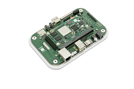
Connect IGEP SMARC Expansion with IGEP SMARC Boards
The IGEP SMARC Expansion connects to the IGEP SMARC Boards through J200 connector.

|
Booting
Before booting, mount J1202 jumper in boot0 position in order to boot from uSD or boot2 position in order to boot from module device (NAND/NOR). Other boot possibilities can be selected (see SMARC EXPANSION manual)
"Under the hood" the bootloader is preparing to load the linux kernel. The linux kernel loads and initializes the hardware and mounts the root file system. The firmware in its microSD card consists of a minimal Linux-based distribution with a lite X Window System and GNOME Mobile based applications created with Poky Platform Builder.
You can use the mouse and the keyboard to dive into the desktop.

|
Network
You may now plug the Ethernet cable into the 10/100 Ethernet jack of the board to get network access. The default firmware configures the Ethernet device with dynamic IP address (via DHCP).
Remote connection via Serial interface
Overview
Serial header (J801) lets you debug system with an USB to 3V3 TTL level serial like TTL-232R-3V3 converter from FTDI or compatible reference. The TTL-232R-3V3 converter has 6 pins and IGEP SMARC EXPANSION add a 7th way (3v3 power). The next image shows how to connect it:
 |
Setting up connection
Open the serial on your PC using your preferred serial communications program (minicom) and configure the port as follows:
- 115200
- 8N1
- no flow control (either software or hardware)
Open the serial port and the debug shell prompt should appear.
A detailed guide on how to connect via serial debug port can be found by following this link: Using serial debug port to communicate